
How the Touch Drive System Works

The “Touch Drive” system introduced the 1986 Ford Ranger was an early electronic shift-on-the-fly 4WD system. It replaced the traditional floor-mounted manual transfer case lever with an overhead push-button console and an electric shift motor.
The system relies on an interplay of electronic controls and mechanical execution to change modes between 2-Wheel Drive High (2H), 4-Wheel Drive High (4H), and 4-Wheel Drive Low Range (4L):
1. Control Logic & Overhead Console
Because the electric shift system was introduced mid-generation, Ford integrated the control buttons into an overhead console mounted above the rearview mirror rather than modifying the dashboard. When the dash was updated for 1989, a place was created in the dash for the “Touch Drive”. When you press a button (such as 4×4 or Low Range), a signal is sent down to a dedicated shift control module located under the dashboard. This module acts as the “brain,” validating the shift parameters before executing the command.
2. The Electric Shift Motor
Once the control module approves the shift request, it routes power to a 12-volt DC electric shift motor mounted directly to the rear of the BorgWarner transfer case.
This motor turns a small triangular shift shaft inside the transfer case.
A built-in plastic contact wheel (encoder assembly) inside the motor housing tracks the physical position of the shaft, signaling back to the control module when the transfer case has successfully engaged the requested gear. Indicators on the dash cluster and small amber lights on the overhead console illuminate once the shift is physically completed.
3. Shifting “On the Fly” (2H to 4H)
The Touch Drive system allows you to shift from 2-wheel drive to 4-wheel drive high at any legal speed. When you press the 4×4 button while moving:
- An electromagnetic clutch inside the transfer case spins up the front driveshaft to match the speed of the rear driveshaft.
- Once the speeds are synchronized, the mechanical shift fork locks into place, splitting power 50/50 to the front and rear axles.
4. Safety Interlocks for Low Range (4H to 4L)
To prevent severe powertrain damage, the control module enforces a strict mechanical interlock sequence before allowing a shift into 4-Wheel Drive Low:
- The vehicle must be stopped or moving under 3 mph.
- If equipped with an automatic transmission, the shifter must be placed in Neutral.
- If equipped with a manual transmission, the clutch pedal must be fully depressed.
- If these conditions aren’t met, the control module will block the shift motor from rotating into the low-range gear set.
Alternative Switches for Touch Drive
Ford’s Touch Drive system made it possible to shift the Ranger’s electric-shift transfer case with the push of a button. When everything is working, it’s a convenient system.
The problem is that these trucks are getting old, and replacement Touch Drive switches, control modules, and other components aren’t always easy to find. Used parts can also be difficult to locate.
If you’re trying to keep a factory-equipped Ranger, Bronco II, or Explorer original, repairing the factory system is still the preferred approach. But what if you can’t find the parts? Or what if the truck is a dedicated trail, hunting, work, or off-road vehicle where originality isn’t important?
There is another option. Forum members ‘franklin2’ and ‘Ron D’ explain a workaround using a momentary switch. This IS NOT a factory-style replacement but a way to control the transfer case when the original Touch Drive system is no longer practical to repair.
Warning!
One of the problems with this bypass is a 3rd party operating your vehicle. Or a child riding with you (should be in the car seat I know, but) being curious and playing with the switch. A bunch of the functions of the original computer was the safety of the driveline/transfer case. You will get a reliable working 4×4 system, but you will lose these features. Like;
Shift on the fly. Can’t do it, you will have to stop traveling to go into 4×4.
You had several conditions to go into 4 low. The vehicle could not be moving, you had to be in neutral, etc.
None of this is a problem if you treat this like a manual transfer case. The only difference is that you’re toggling a switch instead of pulling a lever.
Franklin2’s Explanation of Using A Momentary Switch
I highly recommend buying the proper spring-loaded switch, since I found you have to bump the switch to move the transfer case motor. The switch you need is a center off, spring loaded up and down switch. It will have six terminals on it:
GlideForce SWT-TOG-MOM-4W
DPDT-CO 30 Amp Momentary Toggle Switch – Surplus Center
This is a 12-volt DC, 30-amp, DPDT center-off momentary toggle switch with four terminals. It is designed to reverse the polarity of a DC motor, which makes it well suited for controlling the electric shift motor on the transfer case.
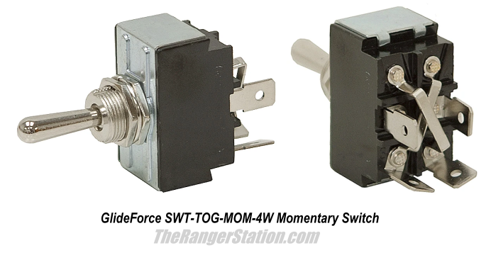
Also, you will notice the switch I linked to is good for 30 amps. You are controlling the motor directly, none of the factory switches are designed to handle the current load of the motor directly.
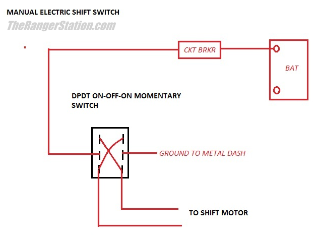
If you look at the pictures of this switch, it has a “X” wired in it. You cut the wires on the transfer case motor itself and run two wires (I ran a small cable) from there along the frame up into the engine compartment.
I then mounted the switch under the dash and ran four wires to it. Two are power and ground. The other two go out under the hood and splice into the motor wires you ran. The power wire hooks directly to the battery + with a circuit breaker.
On the switch, the motor wires can hook to the center terminals. The power and ground can wire to either the top of the “X” or the bottom of the “X”. When you move the switch off center, it connects the motor to the top of the “X” or if you move the switch the other direction, it connects the motor to the bottom of the “X”. This is basically swapping the polarity of the power going to the motor depending on which way you move the switch.
I labelled my switch “2WD” on one side, and “4WD” on the other side. When I would bump the switch in the “2WD” direction it would move the transfer case into 2WD. To keep from straining things, I would only momentarily bump the switch. The factory computer must have used a lower voltage on the motor, because a straight 12-volts moves the motor very quickly, another reason to just bump the switch.
When I would bump the switch in the “4WD” direction, it would move the transfer case out of 2WD and into 4HI. Once in a while I would not bump it enough and you would hear a slight grinding noise. One more bump would do it. I would come to a stop, put the transmission in neutral, and then give it several bumps in the “4WD” direction, this would put it in 4LO. You can feel it sometimes going into gear.
I used this for years and was able to reliably use 4WD when I needed it. Unlike the computer system which only worked when it wanted to.
Ron D Explanation of The Shift Motor Operation
Ford Ranger shift motors work the same as the power window motors. Two wires with 12-volts on one wire and Ground on the other causes the motor to spin clockwise. Reversing the polarity, Ground / 12-volts, causes the motor to spin counterclockwise.
Window up window down.
The transfer case shift motor’s two wires are BOTH GROUNDED when not in use. Each motor wire has its own 30 amp 5-pole relay.
When the relay is off its wire to the motor is Grounded.
When the motor needs to be activated then only one of the relays needs to be activated, disconnecting it from ground and connecting to 12-volts, because the other wire is already a ground.
Most of these motors have a Thermal Limiter circuit breaker inside. This means that when the motor’s mechanical mechanism hits too much resistance (sudden high amps) the Limiter opens, cutting ground or 12-volts, doesn’t matter which, so the motor won’t turn anymore.
There are no other “limit switches”. Just the Thermal Limiter on windows or the shift motor.
The shift motor has a mechanical stop on its drive wheel because you could damage the transfer cases shift rod if it was used as the resistance stop for thermal limiter.
So, all you need to move the shift motor are two 30 amp, 12-volt, 5-pole relays and a 20 amp fused circuit. You want the fuse to blow before the wires or relays.
4WD Positions & Indicator Lights:
The position of the shift motor is the hard part, but Ford has done the hard work with the contact plate and five contacts. The contact plate is on the drive gear; the part that turns as the motor turns the shift rod in the transfer case.
You would have four LEDs (12v lights) that all have 12volts when the key is on.
There are five position wires on the shift motor.
One main wire, a yellow/white wire (which would be a full-time Ground wire) and then four wires, one to ground each light bulb.

This is what the controller uses to determine shift rod position.
Open means NOT connected to yellow/white (ground) wire.
Shorted means connected to yellow/white (ground) wire.
You would use light bulbs instead numbered 1 to 4 from left to right:
2WD (2HI) would be:
1 on
2 off
3 on
4 off
4WD High (4HI) would be:
1 off
2 off
3 on
4 on
4WD Low (4LO) would be:
1 on
2 on
3 off
4 off
Or maybe more simply than the chart above:
| Transfer Case Position | Contact 1 | Contact 2 | Contact 3 | Contact 4 |
|---|---|---|---|---|
| 2WD / 2H | ON | OFF | ON | OFF |
| 4HI | OFF | OFF | ON | ON |
| 4LO | ON | ON | OFF | OFF |
ON means the contact is connected to the common/ground circuit.
OFF means the contact is open.
How Franklin2 Wired His Indicator Lights
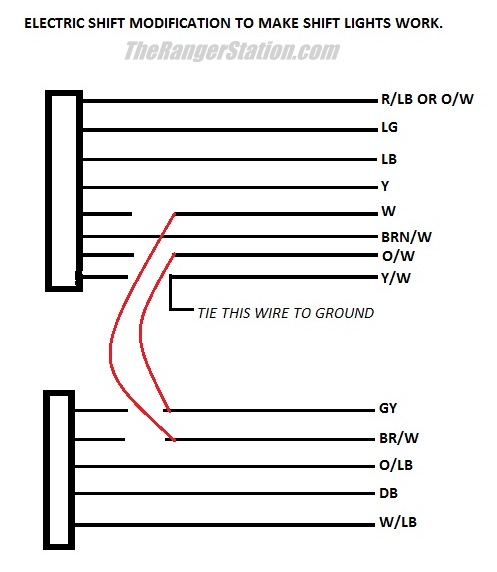
I only wired two lights. On mine I wired in the original lights in the console. On a friend’s I converted I added two lights in the same metal bracket that held the switch under the dash. I only needed a 4WD HI light and a 4WD Low light. If I bumped the switch several times in the 2WD direction, and both lights were out, I was in 2HI. Bump it in 4×4 direction till the 4HI lit, I was in 4WD High. Keep bumping it a lot till the 4LO light lit, I was in 4WD Low. I didn’t care about neutral either, though I am sure it would be easy to find, no lights and it will not move in any gear.
My priority was to keep it simple. I did not want to duplicate the complicated Ford system. Below I attached a picture for the modifications needed to make the lights work on a 1986 ranger system. This truck had the shift computer under a panel on top of the dash on the pass side. The diagram represents the two large wiring plugs going into the computer.
Supplying Power
Do not simply connect the motor to an unprotected battery feed. Franklin2 ran power directly from the battery and protected the circuit with a circuit breaker. Ron D suggested a 20-amp fuse. Make sure you’re using a wire gauge long enough to handle the amps and the length of the wire. See: Selecting The Proper Wire Size
Verify Your Wiring
The wire colors and connector locations can vary between years and applications. Don’t assume that a wire color or pin number from one Ranger applies to every Touch Drive-equipped Ranger or Bronco II. Use the wiring diagram for your particular truck before connecting anything to the position circuits. The chart above is useful for understanding how the position contacts work, but it should not be treated as a universal pinout for every year.
Before You Modify Your Truck
Keep the following in mind:
- Diagnose the factory system first if the original components are still present.
- Protect the new motor circuit with an appropriately sized fuse or circuit breaker.
- Use wiring capable of handling the motor current.
- Secure the wiring away from heat and moving components.
- Never assume the transfer case is in a particular position simply because you moved the switch.
- Use short switch “bumps” rather than holding the motor continuously.
- Put the transmission in Neutral when shifting into or out of 4LO.
- Verify the position-contact wiring for your specific year and system.
- If you add indicator lights, verify their operation before relying on them.
TRS Forum Discussion
This article was developed from information shared by TRS forum members in the original discussion:
Alternative Switches for Touch Drive
The discussion includes the switch information, wiring, transfer-case position contacts, indicator-light modifications, and real-world experience with the conversion.
Disclaimer
This modification bypasses portions of the factory 4WD control system. Electrical work and transfer-case operation can result in vehicle damage or injury if performed incorrectly. Verify the wiring and operation for your specific vehicle before modifying the system. The information presented here is based on the experiences and information shared by TRS members and should be considered a starting point for your own research, not a substitute for the factory service information for your vehicle.
Related Articles
The 1983-2011 Ford Ranger 4WD System
Checking 4WD Shift Module Circuits (1994-Older)
Ford Ranger 4×4 Module Diagnosis (1994 & Older)
1995-2000 Ford Ranger 4WD Control Module
Troubleshooting Procedure – 1995-2000 4WD Module
Article Contributors
Thanks to forum members franklin2 and Ron D.
About The Author
Jim Oaks is the founder of TheRangerStation.com, the longest-running Ford Ranger resource online since 1999. With over 25 years of hands-on experience building and modifying Ford Rangers — including magazine-featured builds like Project Transformer — Jim has become one of the most trusted authorities in the Ford Ranger off-road and enthusiast space.
Since launching TheRangerStation.com, Jim has documented thousands of real-world Ranger builds, technical repairs, drivetrain swaps, suspension modifications, and off-road adventures contributed by owners worldwide. TheRangerStation.com has been referenced in print, video and online by enthusiasts, mechanics, and off-road builders looking for practical, and experience-based information.