
Introduction:
The 2019-2023 Ford Ranger 4×4 offered an FX4 off-road package and the 2021-2023 Ford Ranger 4×4 offered a Tremor off-road package that was an upgrade to the FX4 package.
FX4 and Tremor Packages:
FX4 Off-Road Package (914) Includes:
- “FX4 Off-Road” bodyside decal
- 17” Off-Road OWL Tires (TGT)
- 18” Off-Road OWL Tires (TFP)
- Electronic-Locking Rear Differential
- Exposed Front Tow Hooks
- Exposed Steel bash plate
- Off-Road Screen in Cluster
- Off-Road tuned suspension
- Remove front air dam
- Skid Plates: fuel tank, transfer case and front differential
- Terrain Management System™
- Trail Control™
- LT 265/65 R17 A/T OWL Tires (TEW) (Optional) (30.6″x10.4″x17)
Tremor Off-Road Package (914T) Includes:
- “Tremor” bodyside decal
- Off-road tuned suspension
- FOX™ 2.0 monotube dampers with rear piggyback reservoirs
- Rear multi-leaf springs
- 9.7″ of ground clearance (The Tremor suspension is lifted 20mm (0.8-inches) higher than a stock 4×4 Ranger)
- 32″ General Grabber A/TX all-terrain off-road tires (actually 265/70/17 tires which equate to 31.6″x10.4×17)
- 17″ Magnetic-painted aluminum wheels
- 6-switch auxiliary power pack
- Black exposed steel bash plate
- Terrain Management System™
- Trail Control™
- 4×4 electronic rear locking differential
- Hoop Steps
- 2 rear tow hooks (n/a with Tow Package)
- Magnetic-painted wheel-lip moldings with 1″ wider offset
Advantages Of FX4 and Tremor Off-Road Packages:
The advantage to the FX4 and Tremor models is that they give you:
- Locking rear differential
- Front tow hooks
- Skid plates
- Terrain Management
- Trail Control
- “Off-road tuned suspension”
Personally, I wouldn’t buy a Ranger with the Tremor package if you have any plans of doing suspension modifications. When you shop for suspension kits to lift this truck you’ll see that they state “Does NOT work on models equipped with Tremor package.”
To understand Terrain Management and Trail Control, check out Ford Ranger Trail Control And Terrain Management.
I Bought A Standard 4×4 Ranger Without The FX4 or Tremor Package:
Locker:
You can add a rear locking differential by either salvaging a rear axle from a 2021-2023 FX4 Ford Ranger or purchasing an aftermarket rear locker.
ARB offers the ARB RD245 Air Locker (BUY HERE) for the Ford Ranger M220 rear axle.
You may be able to swap in a factory rear axle from a Ranger that has the factory locker. You would have to replace auto start/stop button with one that has the e-locker button next to it and turn it on in Forscan under BCM. The power wire for e-locker is in the lower harness on the driver side frame rail.
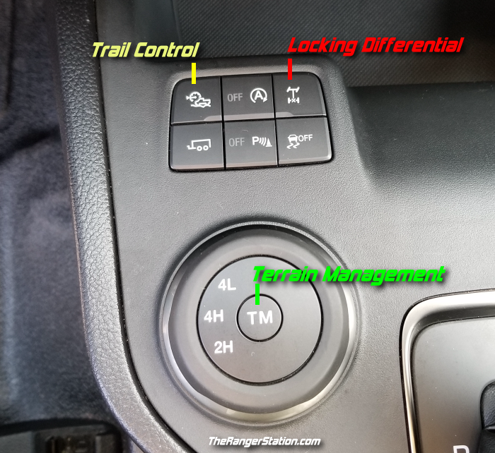
Trail Control / Terrain Management:
You can add Trail Control and Terrain Management by purchasing the Terrain Management Switch KB3Z-14B596-AB and replacing the stock 4WD switch on your console, use Forscan to access the IPC Module (Instrument Panel Cluster) and enabled ‘Selectable drive mode’.
What Size Tires Can I Fit On A Stock Truck Without A Lift:
In 2019 Ford loaned me a 2019 Ford Ranger for 6-months (See The ‘Loan Ranger’ 2019 Ford Ranger FX4) that I used to complete the Trans America Trail and attend Overland Expo West. I left the suspension stock to show what a stock Ford Ranger could do, but I swapped out the tires for a set of Cooper Discoverer STT PRO 265/70/17 mud terrains.
Stock: 265/65/17 (30.40×10.40×17)
Coopers: 265/70/17 (31.93×10.70×17)
The new tires are 1.53-inches taller than stock, so the truck picked up 3/4″ of ground clearance.
These tires did not rub on the intrusion bars (crash bars) at full lock turning left or right.
Intrusion Beams:
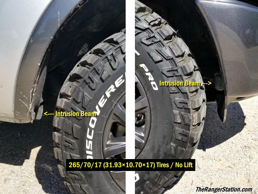
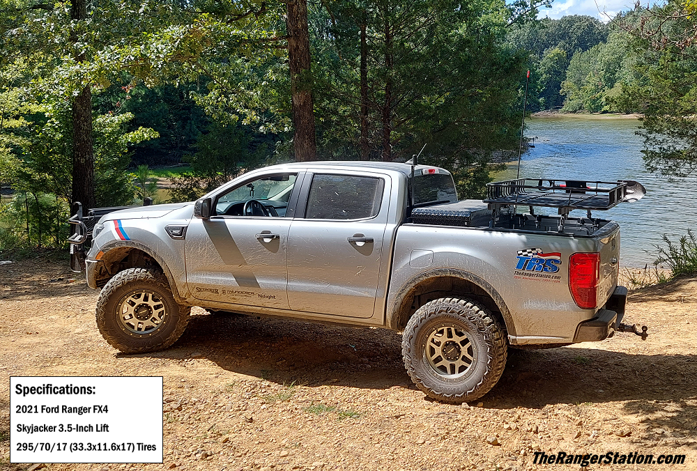
There are intrusion beams (crash bars) in front of and behind the front tires. It’s my understanding that they’re there to help prevent the front wheel from being shoved into the foot well (floorboard) during a collision. In the photo above you can see that the 265/70/17 (31.93×10.70×17) tires are as big as you’re going to get on a stock truck with rubbing on these bars
Fortunately, companies make a replacement to allow more tire clearance while still maintaining safety.
When I added a Skyjacker 3.5-Inch Lift and 295/70/17 (33.3×11.6×17) mud terrains I chose to go with the Readylift High-Clearance Anti Intrusion Beams P/N 67-2900.
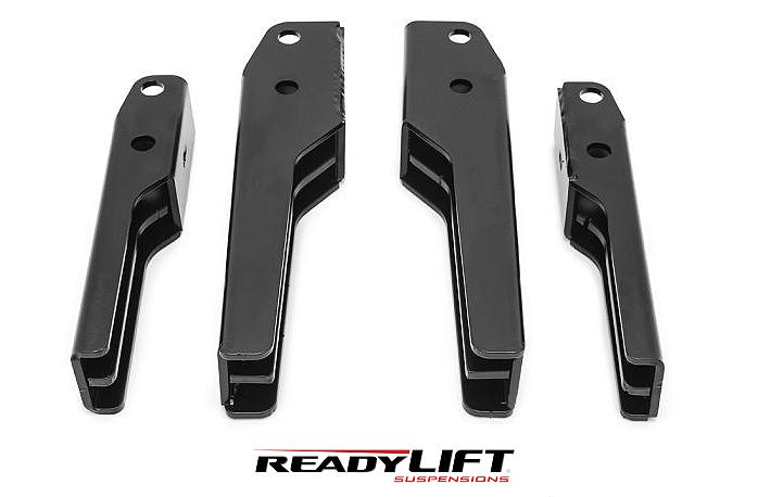
ReadyLIFT states that the notched design increases tire turning clearance and allows for up to a 285/70-17 tire (32.7×11.2×17) with their ReadyLIFT 3-inch lift kit. See: Installing Readylift Intrusion Bars.
295/70/17 (33.3×11.6×17) mud terrains ended up rubbing the very edge of the rounded corner on the narrow end at full turn. I resolved it by grinding a 1/4-inch off of the corner with a grinder.
Adding A Suspension Lift And Larger Tires:
Adding a suspension lift allows for more clearance under the truck as well as room for larger tires. Larger tires also help add to the clearance height. More clearance can be necessary when driving over harsh terrain, when having to forge through water, and is even a requirement when traversing challenging forest roads.
![]()
Whether or not you need a suspension lift is really dependent on what you’re using the truck for. I’ve done the Trans America Trail with just the addition of more aggressive tires. Hard trails, rock crawling, and bogging through deep mud could require more lift and taller tires.
You can find suspension lifts for the 2019-2023 Ford Ranger in the 2-inch, 2.5-inch, 3-inch, 3.5-inch, and 6-inch lift sizes.
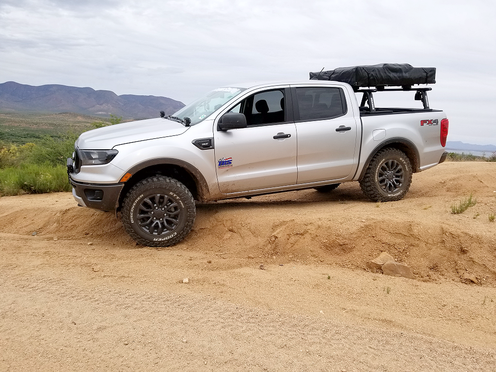
The 2021 Ford Ranger FX4 (TRS-3) shown above uses a 3.5-Inch Skyjacker Suspension, Pro Comp Wheels, 295/70/17 (33.3×11.6×17) mud terrain tires and a set of ReadyLIFT Intrusion Beams (crash bars) to allow the tires to fit. I chose to use an aftermarket crash bar instead of just removing the factory crash bar for safety reasons.
Stock Tire Size:
- 265/65/17 (30.40×10.40×17)
Largest Tire Without A Lift or Mods:
- 265/70/17 (31.93×10.70×17) (Check Out: Largest Tire On A 2019 Ford Ranger Without A Lift)
Largest Tire With a 2-Inch Lift:
- 255/75/17 (32.1x10x17) tire on a factory wheel
- 265/65/18 (31.6×10.4×18) tire on a factory wheel
- 265/60/18 (30.5×10.4×18) tire on a 18×9 wheel with 6.5-inch backspacing and +18mm offset
- 265/60/18 (30.5×10.4×18) tire on a 18×9 wheel with 6.5-inch backspacing and +30mm offset
Largest Tire With A 2.5-Inch Lift:
- 265/65R18 (31.6×10.4×18)
Largest Tire With A 3-Inch Lift
- 285/60R18 (31.5×11.2×18) 18×9 +18 offset
- 275/65R18 (32.1×10.8×18) 18×9 +30 offset
Largest Tire With A 3.5-Inch Lift
- 285/65r18 w/18″ and stock back spacing (32.6×11.2×18)
- 295/70/17 (33.3×11.6×17) with ReadyLIFT Intrusions Beams and a little trimming on the corner of the beam
Largest Tire With a 6-Inch Lift:
- 35×12.50 tire on 20×9 wheel with 5.5-6″ back spacing
- 305/65r18 (33.6x12x18) tire on 18×9 wheel with 5″ back spacing (33.6x12x18)
- 33×12.50 tire on 17×9 / 18×9 / 20×9 wheel with 4.5″ back spacing
- 305/55-R20 (33.2x12x20) tire, on a 20 x 9 +12mm wheel
For even more information along with tire and wheel sizes, check out our 2019-2023 Ford Ranger Wheel & Tire Guide.
Tires:
Speaking of tires, a good tire is important to make sure that your Ranger can get traction on unmaintained trails or roads. Just because it shows up on the map as a county or forest road doesn’t mean it’s been maintained.
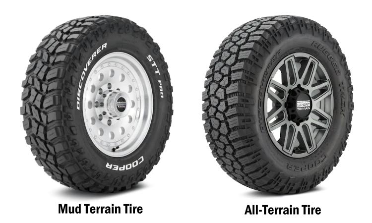
I suggest either a good set of all terrain or mud terrain tires. You’ll get more miles out of a good all terrain than a mud terrain. Make sure you have a matching fullsize spare and a good jack and lug wrench. If your truck is lifted and has taller tires, your stock jack my not have the ability to jack the truck high enough to get the tire off of the ground so you can change it. I actually carry a mini floor jack and a 4-way lug wrench in my Ranger.
You’re building an overlanding truck, not an off-road truck, so you really don’t need a tire over 33-inches.
Upgraded Bumpers & Grill Guards:
Depending on what you’re building your Ranger for, you may decide that you need a good winch bumper and/or grill guard. Not only do they help protect the front of your truck, but they also provide a place to mount a winch, recovery points, and lights.
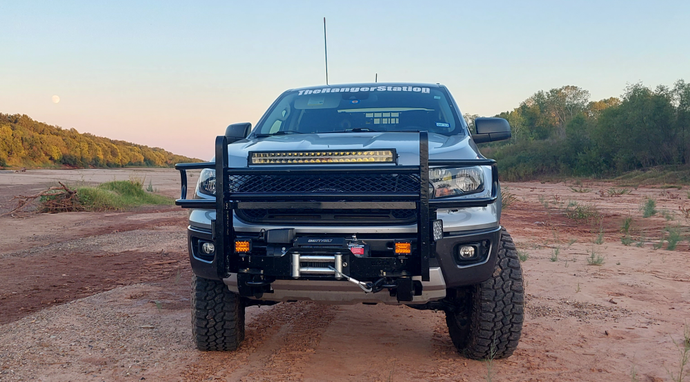
I don’t like having lights mounted above the hood or the cab. It results in the lights glaring off of the hood.
You’ll notice that my lightbar is mounted at the top of my grill guard, and my ‘ditch lights’ are mounted on the side of the grill guard and angled off to the sides. The lights are just as effective mounted in these positions with the problem of light glare.
There are numerous companies that make bumpers and grill guards for your Ford Ranger. I’m not going to go over all of them here.
This Ranger was supposed to feature a winch bumper from Calmini, but they were unreliable and never delivered. With the deadline passed and an offroad adventure quickly approaching, I had no choice but to build my own.
The bumper uses a Westin Winch Mount Plate for an F-150 that I got from Amazon for $100. The grill guard is extra heavy duty and built by Ranch Hand for a Dodge Ram. These grill guards use steel angle to brace the tubing to prevent it from bending. The winch plate is slightly wider than the one for the Ranger. I just had to drill new mounting holes. The center of the grill guard was cut out and narrowed and then welded to the winch plate. This heavy-duty bumper cost me less than $200. Don’t be afraid to think out of the box and build your own bumper if you need to.
What Size Winch:
For trucks, it’s simple. Take the gross vehicle weight rating (GVWR) and multiply it by 1.5. The 2019-2023 Ford Ranger has a GVWR of 6,050. 6,050 x 1.5 = 9,075 lbs. My 2021 Ford Ranger uses a Smittybilt XRC 9.5 9,500 lb winch.
Upgraded And Additional Lighting:
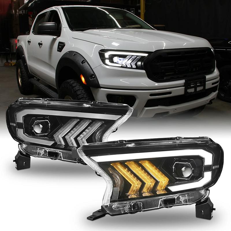
If your Ford Ranger didn’t come with LED headlights, you can upgrade them. For me, brighter lights are a necessity. The rural roads here in Texas have a 75-MPH speed limit, and a feral hog, loose cow, deer, and armadillos can come at you fast in the middle of the night. You don’t need to purchase the factory LED headlight assemblies if you don’t want, you can purchase aftermarket LED headlight assemblies.
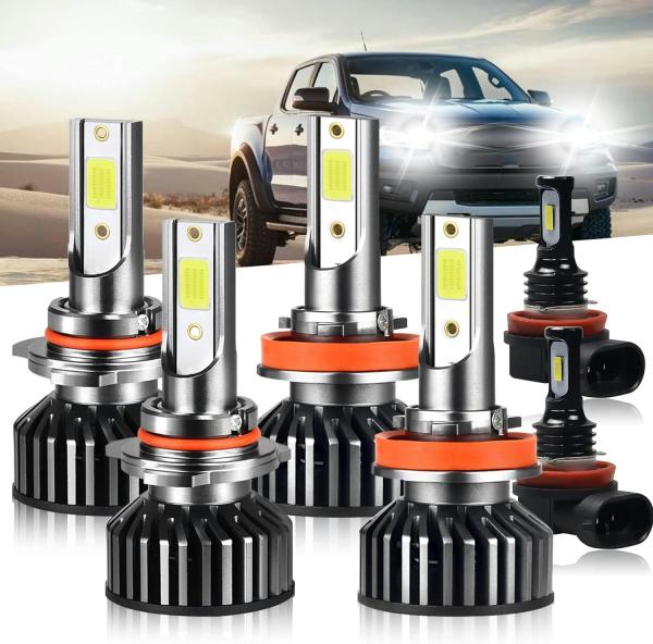
If you don’t want to swap out your headlight assemblies, you can upgrade by simply swapping your headlight bulbs To LED Bulbs. Check Out: Upgrading 2019+ Headlights To LED.
- H11 – Fog Lights
- H11 – Low Beam
- 9005 – High Beam
Adding Auxiliary Switches:
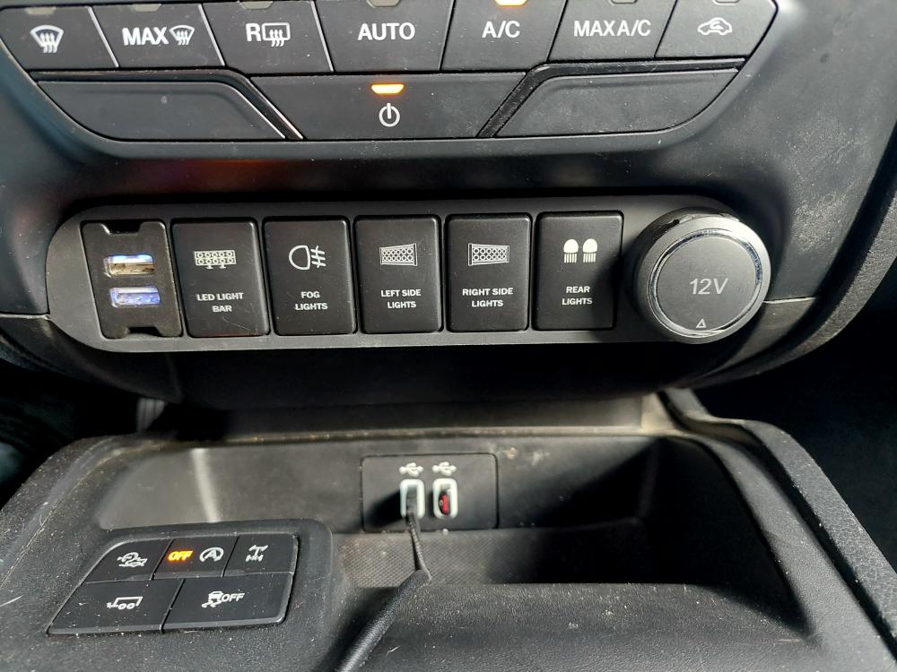
If you plan on using your Ranger to do any off-roading, overlanding, or just working at night, you’ll probably want to add auxiliary lighting. If you didn’t purchase a Tremor package with the upfitter (auxiliary) switches, you’ll need to add auxiliary switches to control them.
If you did get the Tremor package, Check Out: Ford Ranger Tremor Auxiliary Switches.
I personally don’t believe that the factory upfitter switches are worth the hassle to install them.
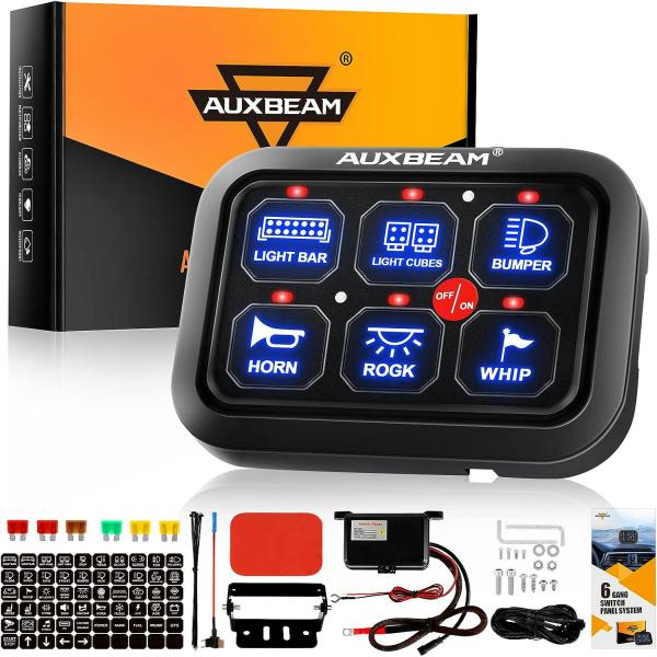
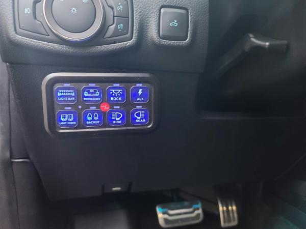
My 2021 Ford Ranger uses an AOB (Air On Board) auxiliary switch panel and switches that replaces the stock panel under the dash where the dual auxiliary outlets are. Check Out: AOB Ford Ranger Switch Panel Install.
Another option would be a complete system such as this Auxbeam 6-Gang Switch Panel.
Communications:
If you plan to do any off-roading or overlanding with other people, trail communications are a vital tool.
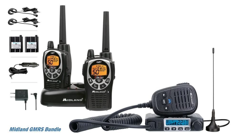
CB Radio use to be the go-to radio for communications off-road. Today GMRS (General Mobile Radio Service) and 2-Meter ham radios have become extremely popular. You’ll need a license to operate a ham radio which requires that you pass a test. GMRS requires a license but it’s only a fee, there’s no test. Another nice thing about GMRS is that you can get portable radios (walkie-talkies) at a pretty reasonable cost that makes communicating with spotters and other people outside of the vehicle much easier.
Check out:
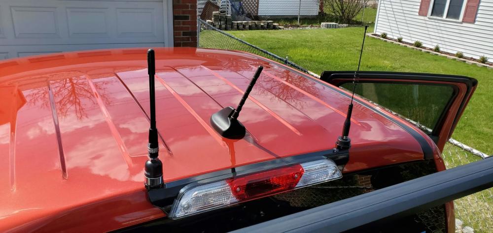
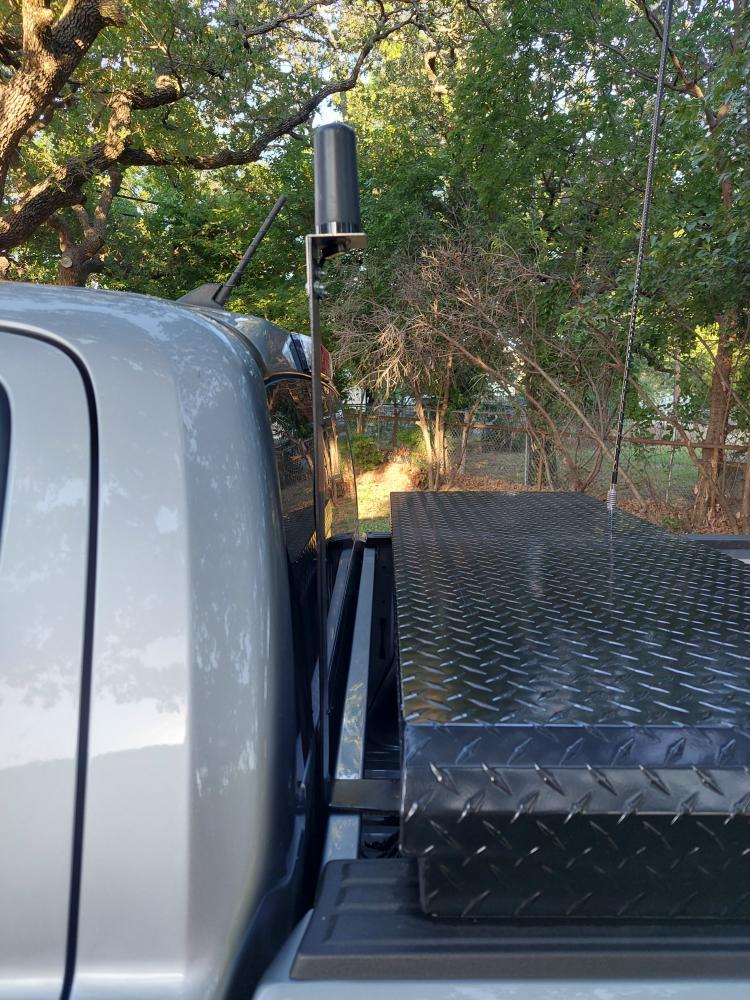
When installing a GMRS or 2-Meter radio you’ll need an NMO antenna mount. Companies like Larson and Bullet Proof Diesel both offer antenna mounts that fit between the truck cab and the third brake light.
I actually made my own antenna mount using flat metal stock bolted to my toolbox. I personally couldn’t see spending over $200 for an antenna mount when I could make my own.
Bed Storage:
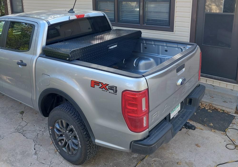
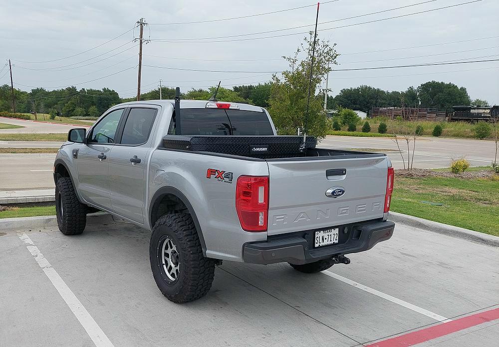
I don’t want a bunch of stuff laying in the backseat of my Ranger, there isn’t much space under or behind the back seat, and I don’t want stuff laying loose in the bed of my truck, so I added a Husky Low Profile Truck Bed Box from Home Depot. I use it to store a mini floor jack (I hate the factory jacks), lug wrench, recovery gear, and tools when needed. I also use it to store a duffle bag and other items when traveling, and I can lock it to keep them safe.
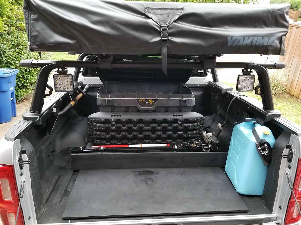
In the setup below I used a Contico toolbox to store and secure items just as mentioned above.
I’m not saying that you need to add a storage box to the bed of your truck, simply suggesting the benefits of it.
On another note, sometimes these boxes can get in the way if you need to haul something. The nice thing about the first box is that it sits up on the bedrails and you can slide lumber and other building materials under it.
Bed Racks:
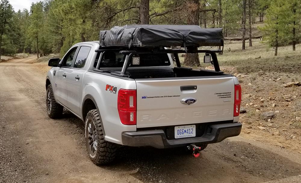
Bed racks can be a helpful and sometimes necessary addition to your Ford Ranger. Above it was a necessary addition for a roof top tent. Below it was added to allow more space to mount and carry the things I’ll need on my overlanding adventures.
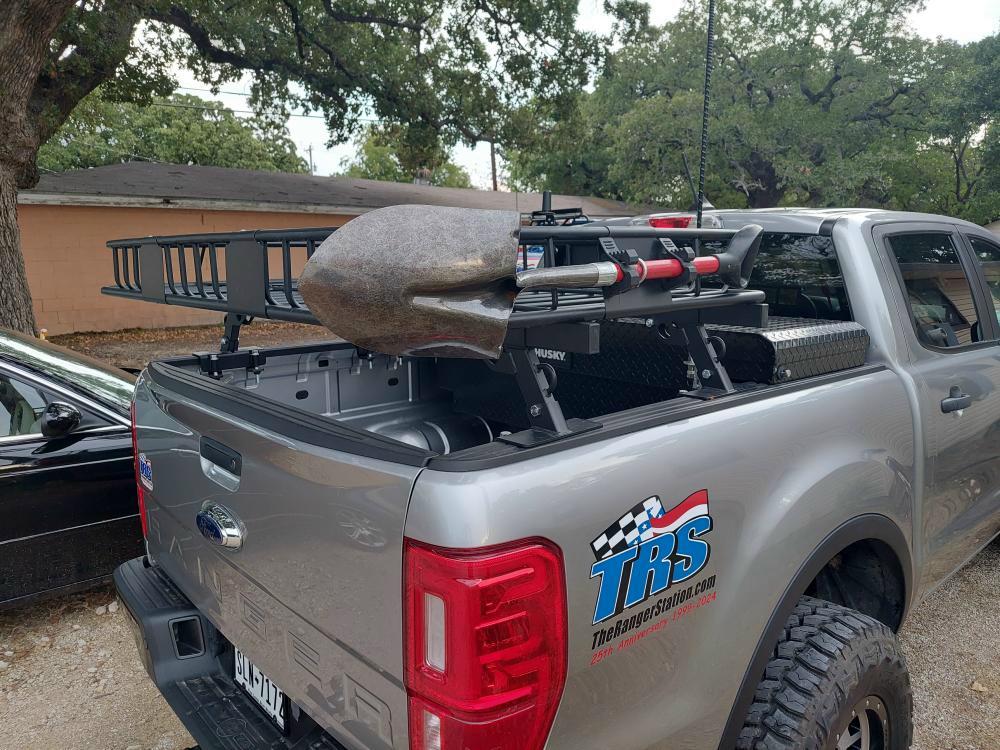
But that doesn’t mean you have to pay a fortune for a bed rack. I built the bed rack above for $300 using the following parts:
Towing:
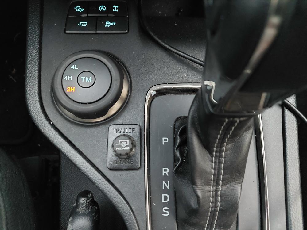
It’s always a good ideal to have your truck setup to tow something in case the need should arise. My Ranger came with a receiver hitch, but the Ranger doesn’t offer an integrated brake controller. Most 2019-2023 Ford Ranger owners install a Tow-Pro Liberty Brake Controller from RedArc.
Check Out: RedArc Tow-Pro Liberty Brake Controller
Conclusion:
Obviously, this page isn’t meant to give you exact instructions on how to build a 2019-2023 Ford Ranger. It will hopefully give you some guidance and things to consider for your own build.