
Introduction
This page provides a factory-style overview of Ford Bronco II cruise control systems, including vacuum-operated and electronic cruise control designs used on 1984–1990 Bronco II models. It explains how each system functions, identifies major components, and includes diagrams to assist with diagnosis, troubleshooting, and repair.
Topics covered include cruise control servos, throttle actuators, control switches, speed sensors, brake and clutch deactivation switches, vacuum dump valves, and amplifier/control modules. Troubleshooting flowcharts and wiring diagrams are included to help identify common cruise control failures such as inoperative systems, failure to hold speed, or disengagement when driving.
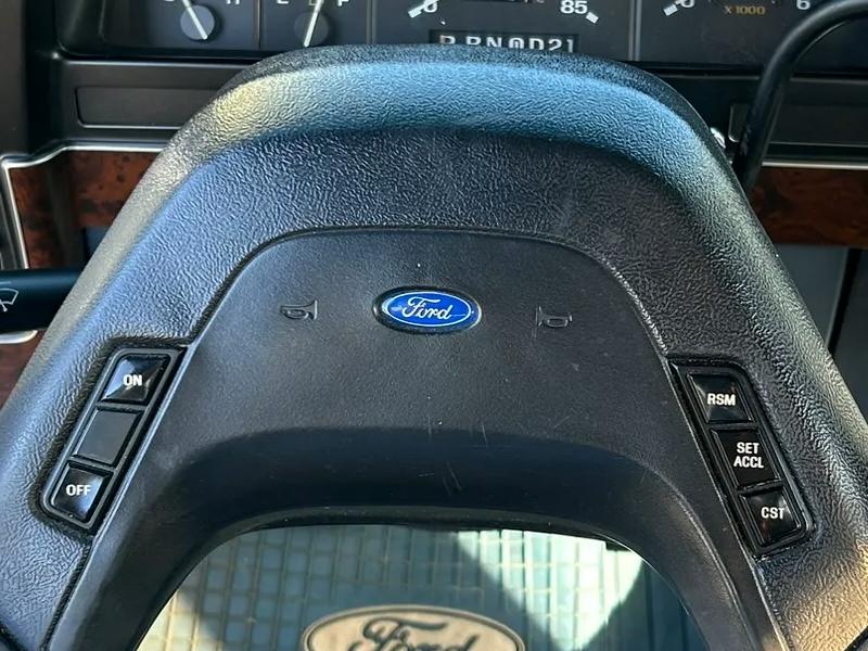
Vacuum Systems
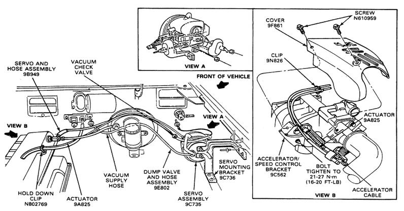
The vacuum-controlled cruise control system consists of the following components:
- Control switches
- Servo (throttle actuator)
- Speed sensor
- Clutch switch (manual transmissions)
- Stop lamp switch
- Vacuum dump valve
- Amplifier assembly
The throttle actuator is mounted in the engine compartment and is connected to the throttle linkage with an actuator cable. The speed control amplifier regulates the throttle actuator to keep the requested speed. When the brake pedal is depressed, an electrical signal from the stop lamp switch returns the system to stand-by mode. The vacuum dump valve also mechanically releases the vacuum in the throttle actuator, thus releasing the throttle independently of the amplifier control. This feature is used as a safety backup.
Fig. 1: Vacuum controlled cruise control system components
Electrical Systems
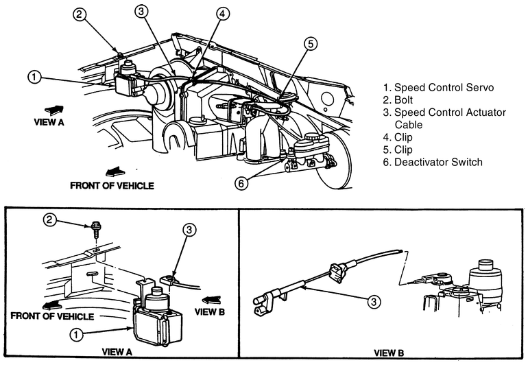
The electronic cruise control system consists of the following components:
- Control switches
- Servo/control unit (throttle actuator)
- Speed sensor
- Stop lamp and deactivator switches
The throttle actuator/control unit is mounted in the engine compartment and is connected to the throttle linkage with an actuator cable. The control unit regulates the throttle actuator to keep the requested speed. When the brake pedal is depressed, an electrical signal from the stop lamp and deactivator switches return the system to stand-by mode. This system operates independently of engine vacuum; therefore, no vacuum lines are required.
Fig. 2: Electronic cruise control system components
Cruise Control Troubleshooting
| Problem | Possible Cause |
|---|---|
| Will not hold proper speed | Incorrect cable adjustment Binding throttle linkage Leaking vacuum servo diaphragm Leaking vacuum tank Faulty vacuum or vent valve Faulty stepper motor Faulty transducer Faulty speed sensor Faulty cruise control module |
| Cruise intermittently cuts out | Clutch or brake switch adjustment too tight Short or open in the cruise control circuit Faulty transducer Faulty cruise control module |
| Vehicle surges | Kinked speedometer cable or casing Binding throttle linkage Faulty speed sensor Faulty cruise control module |
| Cruise control inoperative | Blown fuse Short or open in the cruise control circuit Faulty brake or clutch switch Leaking vacuum circuit Faulty cruise control switch Faulty stepper motor Faulty transducer Faulty speed sensor Faulty cruise control module |
Note: Use this chart as a guide. Not all systems will use the components listed.
Wiring Diagrams:
Here are (2) wiring diagrams that may help as well:
About The Author
Jim Oaks is the founder of TheRangerStation.com, the longest-running Ford Ranger resource online since 1999. With over 25 years of hands-on experience building and modifying Ford Rangers — including magazine-featured builds like Project Transformer — Jim has become one of the most trusted authorities in the Ford Ranger off-road and enthusiast space.
Since launching TheRangerStation.com, Jim has documented thousands of real-world Ranger builds, technical repairs, drivetrain swaps, suspension modifications, and off-road adventures contributed by owners worldwide. TheRangerStation.com has been referenced in print, video and online by enthusiasts, mechanics, and off-road builders looking for practical, and experience-based information.