
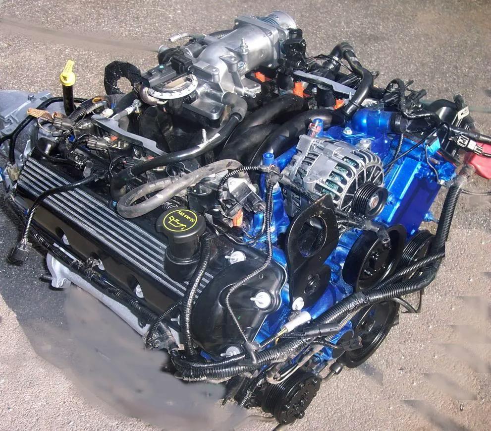
Installing a 4.6L SOHC V8 in a 2001 Ford Ranger
Swapping a Ford 4.6L SOHC V8 into a Ranger takes more than finding an engine that fits between the frame rails. The engine mounts, steering, suspension brackets, oil filter, cooling system, exhaust, fuel system and underhood accessories all have to be worked out. The wiring can be just as challenging, particularly when combining the electronics from two different vehicles.
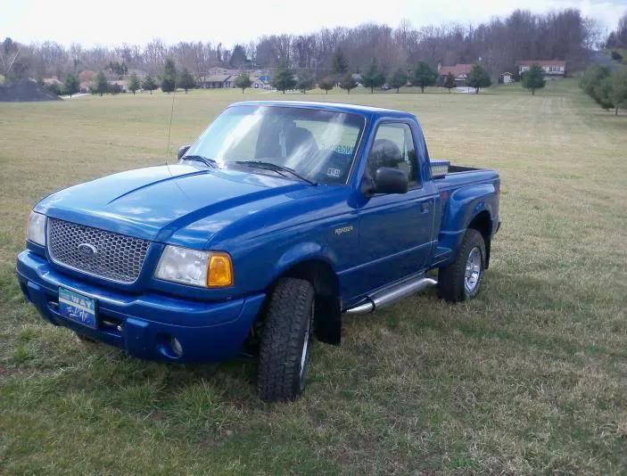
RJAAAAAA documented his 4.6L swap in his 2001 Ford Ranger Edge stepside in the The Ranger Station forums. The engine came from a 2004 Ford Crown Victoria Police Interceptor, commonly identified by its P71 designation. He also obtained the donor computer and other parts needed for the conversion.
The original 3.0L was removed in October 2011. What followed was a series of test fits, fabrication work and adjustments to get the 4.6L installed while retaining as much of the Ranger’s original equipment as possible.
This article covers the parts and modifications used during that installation. The measurements are from this particular truck; they should be treated as a reference rather than dimensions that will automatically work on every Ranger.
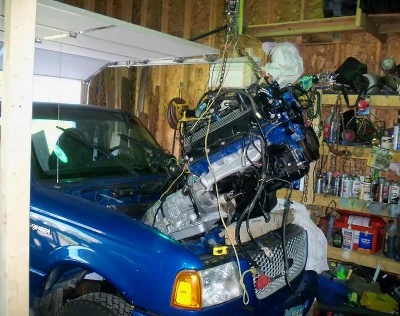
The Donor Engine and Initial Preparation
The donor was a 2004 Crown Victoria Police Interceptor with a 4.6L SOHC V8. When RJAAAAAA removed the engine, he found a tag indicating it was a Ford factory-remanufactured engine dated February 10, 2010.
He also obtained the donor PCM, a complete steering column, a shifter from a 1997 Mustang, the driveshaft and some exhaust components. The donor’s ignition was not a coded-key PATS system, an important distinction when planning the engine-management wiring.
Before installing the V8, he removed the original 3.0L and cleaned up the engine compartment. With the front end exposed, he degreased and pressure-washed the area, scraped and painted the frame, and applied bed-liner paint. He also replaced worn front lower ball joints, a missing front sway-bar link and the truck’s old shocks.
These jobs were easier to complete with the engine out and the front of the truck accessible.
Engine Position, Motor Mounts and Frame Clearance
The first test fit showed that the 4.6L could fit in the Ranger, but it was not a drop-in installation.
RJAAAAAA initially set the engine approximately 1.5 inches to the passenger side of the original engine’s position. The Ranger’s original engine was already offset, so this measurement was relative to that existing position. Moving the engine over helped establish a workable position for the V8 and its exhaust manifolds.
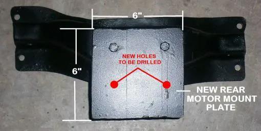
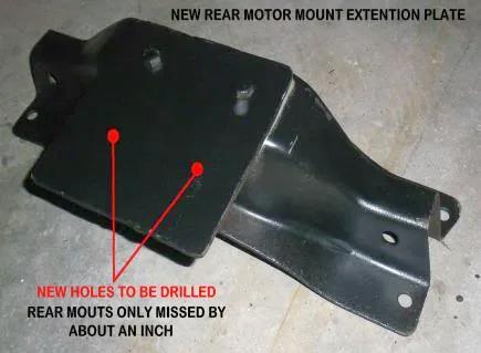
He fabricated motor-mount plates to attach the engine to the Ranger’s original mounts. The transmission mount required a separate bolt-on plate because the donor transmission’s rear mount fell approximately 1 inch short of the Ranger’s original rear crossmember.
The first test fit was performed with the stock Crown Victoria exhaust manifolds and starter removed so the engine could be lowered into position. Once the engine was sitting in the bay, the manifolds were tried again. They interfered with the brackets for the upper control arms, so the engine had to be raised to install them.
Passenger-side shock tower and control-arm brackets
The passenger-side shock tower also needed modification. RJAAAAAA altered the tower, ground material from the upper control-arm brackets and fabricated a filler plate for the shock tower before completing the motor-mount welding.
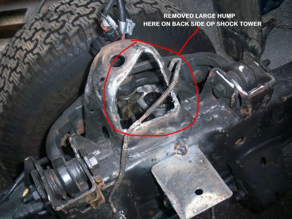
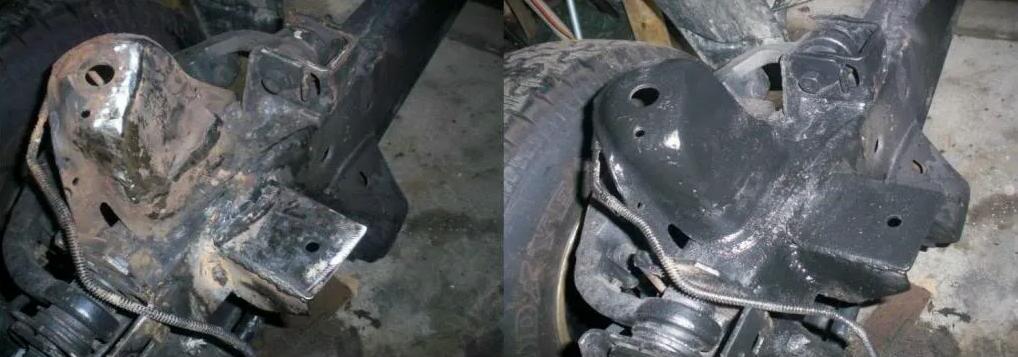
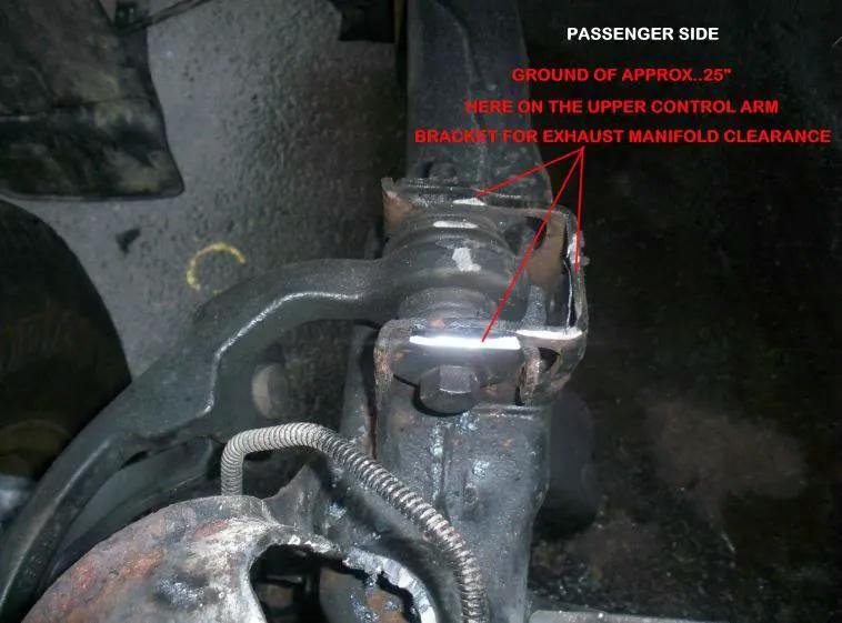
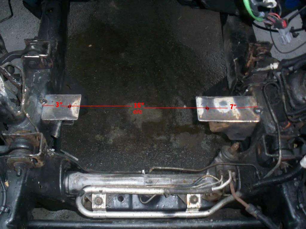
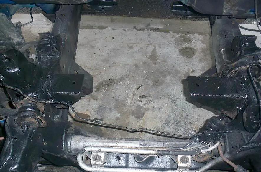
During the next installation attempt, he found another clearance problem: with the starter installed, it contacted the passenger-side upper control-arm bracket. This had not been apparent during the earlier test fit without the starter.
He moved the motor-mount plate holes approximately 3/4 inch forward. He then cut back the rear of the interfering control-arm bracket and ground it down approximately 3/8 inch, leaving it about 1/8 inch inside the frame rail. To gain more room, he heated the frame rail with a torch and hammered it inward approximately 1/4 inch. The bracket was then rewelded and painted.
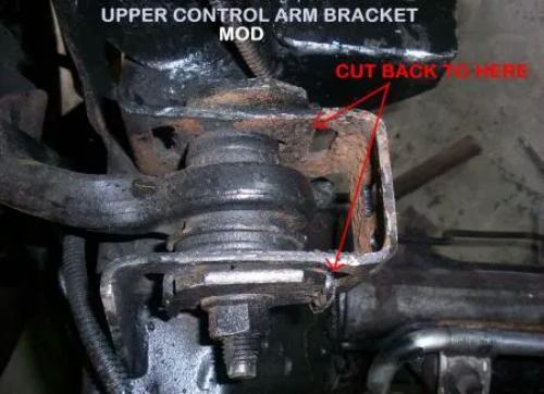
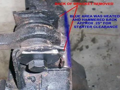
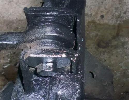
After these changes, the engine dropped into the mounts. The exhaust-manifold flanges still contacted the control-arm brackets, so he used 1/2-inch shims under the motor mounts to raise the engine enough to clear them.
These are substantial modifications to structural and suspension-related parts. Anyone following this example needs to verify the resulting bracket strength, welds, steering and suspension movement, and clearance with the engine under load. The measurements describe what worked on this Ranger, not a universal template.
Exhaust System: Routing the 4.6L Around the Ranger Chassis
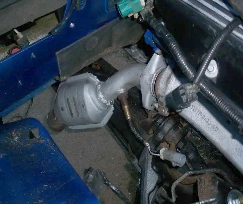
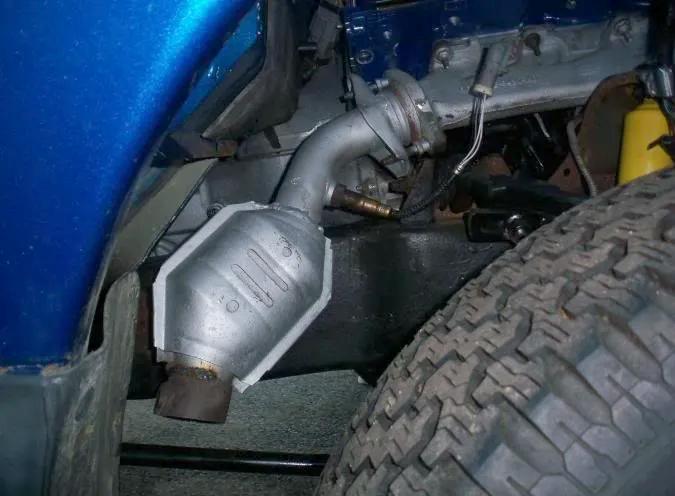
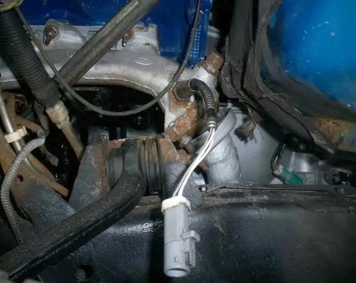
The exhaust was one of the tightest parts of the 4.6L installation. RJAAAAAA retained the stock exhaust manifolds from the 2004 Crown Victoria Police Interceptor, but the manifolds pointed in different directions relative to the Ranger’s frame rails. Rather than trying to force a conventional exhaust system into the available space, he fabricated the connections to catalytic converters and routed the exhaust out through side pipes.
Stock manifolds and catalytic converters
The first step was to install the engine with the stock Crown Victoria exhaust manifolds and starter in place. This exposed the actual clearance problems. The exhaust-manifold flanges contacted the upper control-arm brackets on both sides, so he raised the engine with 1/2-inch shims under the motor mounts. That provided enough room for the flanges to clear.
The manifold outlets were accessible, but the two sides required different exhaust routes. On the passenger side, the manifold and catalytic-converter assembly could turn outward and pass outside the frame rail. There was adequate clearance around the wheel area.
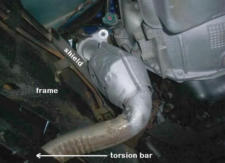
The driver-side manifold pointed inward, toward the transmission. Its exhaust had to pass between the bellhousing and the shield protecting the fuel and brake lines before turning outward. The space between the frame rail and torsion bar offered a route to the outside, but the bends were tight.
RJAAAAAA fabricated the catalytic-converter connections directly from the manifolds. He initially planned to use flexible pipe where necessary and ordered a pair of 50-inch side-exit exhaust pipes from JC Whitney. The side pipes were chrome-finished and long enough to run along the sides of the truck.
Tight bends and flexible connection
Once the side pipes arrived, he continued fabricating the connections between the catalytic converters and the side-pipe inlets. The tight space made the bends difficult, particularly on the driver side, where the exhaust had to work around the bellhousing, fuel/brake-line shield, frame rail and torsion bar.
He ultimately used a short section of exhaust flex pipe to isolate the exhaust from engine movement. That was important with the engine mounted on rubber mounts: the exhaust needed to tolerate some movement without placing all the stress on the fabricated joints or the side pipes.
The finished arrangement used the stock Crown Victoria manifolds, fabricated catalytic-converter connections, a short flexible section and the 50-inch side pipes. It was a custom system built to fit this particular engine position and Ranger chassis, rather than an off-the-shelf exhaust kit.
Mounting the side pipes
For the side-pipe hangers, RJAAAAAA welded small pieces of 1-1/2-inch by 1-1/2-inch light angle iron beneath the door sill. He then adapted the hangers supplied with the side pipes to attach to those brackets.
This gave the pipes their own support along the sides of the truck. The exhaust was no longer relying on the manifold connections or catalytic-converter fabrication to hold the weight of the side pipes.
The build photographs are particularly useful here. They show the passenger-side route outside the frame, the tighter driver-side route, the fabricated connections and the side pipes mounted below the door sills. Those images help explain the routing far better than a generic description of fitting exhaust around a V8 swap.
Important: The clearances in this installation are specific to RJAAAAAA’s 2001 Ranger Edge, its engine position and its suspension brackets. A similar swap needs adequate clearance from the steering, suspension, fuel and brake lines, bodywork and other heat-sensitive components. The exhaust must also be securely supported and checked for leaks before the truck is driven.
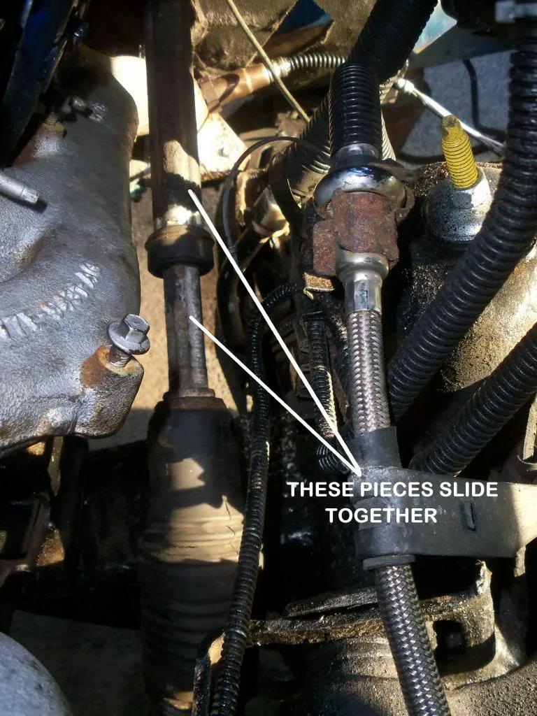
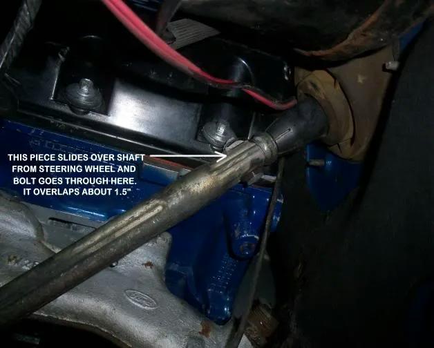
Steering Shaft Clearance
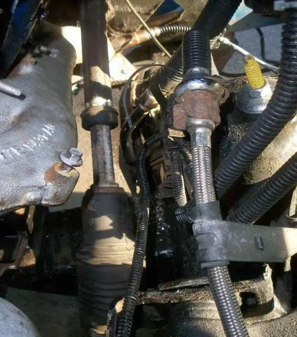
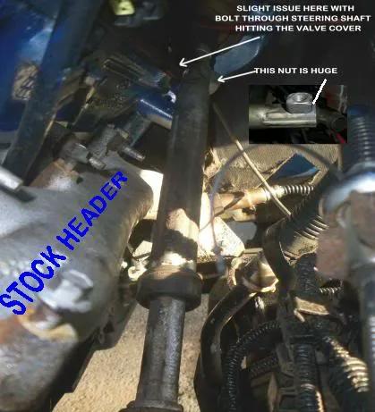
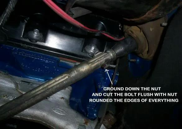
The steering linkage was another tight area. During fitment, the large welded nut on the linkage contacted the edge of the valve cover.
RJAAAAAA ground down the nut, rounded its corners, cut the bolt flush with the nut and ground away the protruding material to gain clearance.
The important lesson is to test the steering linkage with the engine in its final position and the accessories installed. The shaft and linkage must move freely and retain their integrity, with clearance for engine movement. Do not assume that a shaft which clears while the engine is stationary will remain clear when torque moves the engine on its mounts.
Transmission Mount and Driveshaft
The donor transmission’s rear mount did not line up with the Ranger’s original crossmember. RJAAAAAA fabricated a separate bolt-on transmission-mount plate to bridge the approximately 1-inch gap.
When he installed the rear mount and checked the driveshaft, the driveshaft fit without shortening. He reported approximately 3/4 inch of movement at the slip connection.
That result applied to his particular combination of engine position, transmission, mount and rear drivetrain. Driveshaft engagement and available slip travel must be checked on the actual truck, including through the suspension’s range of movement. The fact that the shaft fit this Ranger without shortening does not mean another conversion will use the same length.
Oil Filter Relocation
The Crown Victoria Police Interceptor’s oil-filter mounting arrangement created a problem because the filter adapter also incorporated an oil cooler and the lower coolant outlet. The assembly took up space in an area already crowded by the Ranger’s frame, suspension and engine accessories.
The factory-style police-car adapter could not simply be discarded without considering the coolant connection. RJAAAAAA investigated the differences between the police-car adapter and the standard 4.6L oil-filter mounting arrangement.
He purchased a Trans-Dapt 1127 oil-filter relocation kit and a Trans-Dapt 1427 90-degree bypass adapter. He ultimately found a non-P71 oil-filter adapter at a local salvage yard and added the remote-filter kit to it. He reported that the combination fit well.
The important detail is that he changed the adapter at the engine and used a remote filter setup, rather than trying to retain the original P71 cooler/filter assembly in the crowded Ranger engine bay.
When sourcing parts for a similar swap, check the actual adapter on the donor engine. Not all 4.6L filter adapters are the same, and the police-car oil-cooler arrangement is different from the simpler non-P71 arrangement. Confirm the coolant outlet, oil passages, fittings and hose routing before assembling the system.
Radiator Position and Electric Cooling Fan
RJAAAAAA used a four-core aluminum radiator from a 1999 Mercury Mountaineer with a 4.0L engine. The radiator fit the Ranger’s original brackets, but the fan and shroud required additional work.
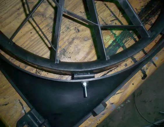
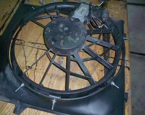
The original Crown Victoria electric fan was too large to fit with its shroud in the available space. Instead of abandoning the fan, he adapted it to the Ranger’s original 3.0L fan shroud.
He cut away part of the Crown Victoria shroud and joined the fan to the Ranger shroud using a section of approximately 1.5-inch poly tubing as a spacer. After bolting the two pieces together, he filled the gap with expanding foam, trimmed it and painted the assembly.
The radiator itself needed to be repositioned to provide adequate clearance from the engine’s harmonic balancer. He removed the lower radiator support to slide the radiator down and behind the original support brackets. This moved the radiator approximately 2 inches forward and 2 inches down.
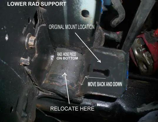
He cut a piece of used radiator hose and placed it on the lower radiator bracket to cushion the support. The upper mounting ears also needed their corners trimmed to clear the underside of the upper crossmember. He planned to make a spacer and bolt the support through the crossmember, and later documented welding an extension onto the lower radiator support.
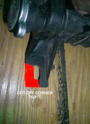
With the radiator repositioned, the fan and shroud could attach to the original brackets, and there was adequate clearance between the harmonic balancer and the fan.
This is a useful example of why cooling-system fitment needs to be handled as a complete assembly. The radiator, fan, shroud, harmonic balancer and mounting supports all affect one another. The radiator’s physical fit alone does not establish that the fan will clear or that the cooling system will perform adequately under load.
Air Conditioning and Heater-Box Modification
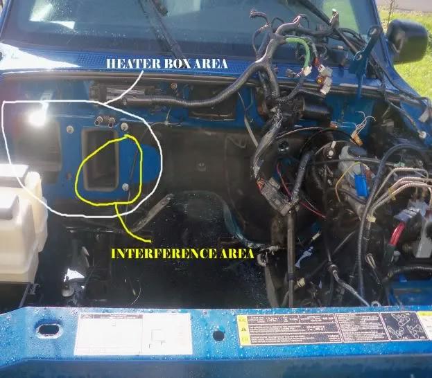
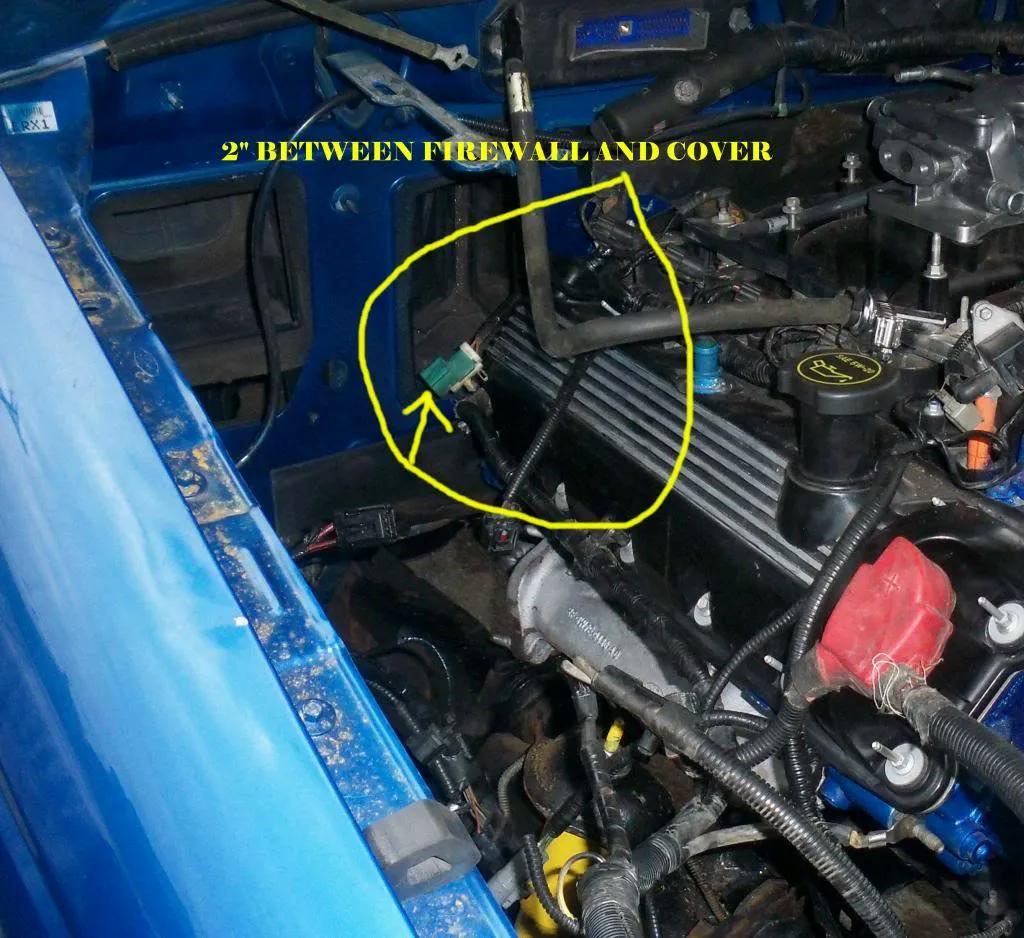
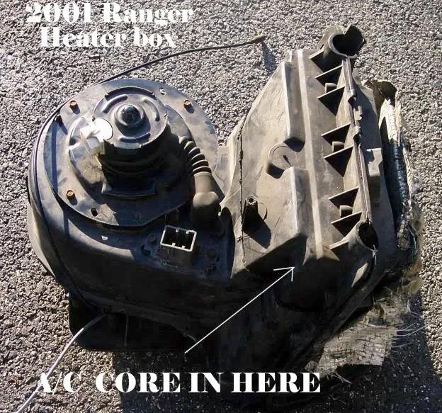
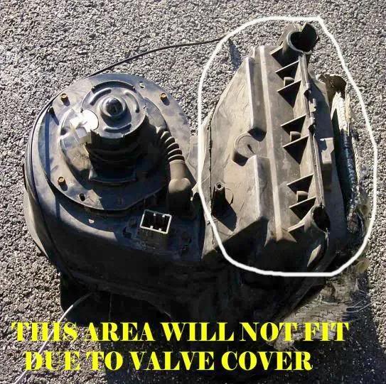
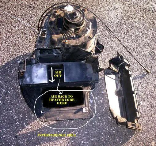
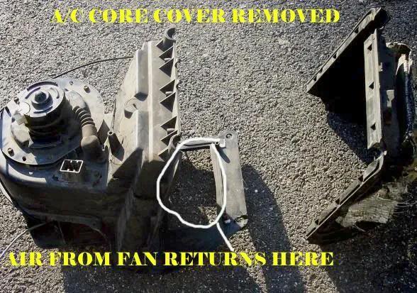
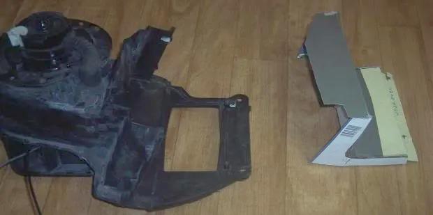
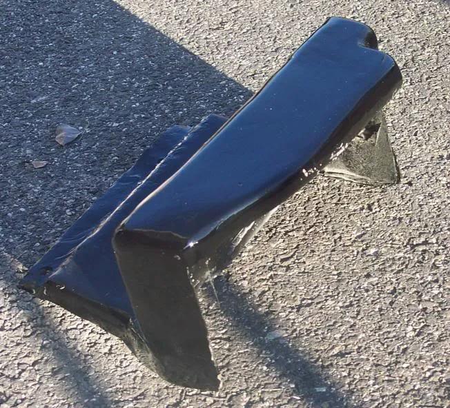
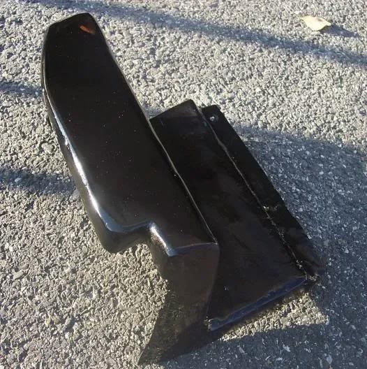
The 4.6L created a major clearance problem at the passenger-side head and valve cover. The Ranger’s air-conditioning evaporator coil protruded too far from the heater box to clear the engine.
RJAAAAAA wanted to retain heat and initially explored ways to work around the interference. The solution he completed involved removing the evaporator coil and modifying the heater box itself.
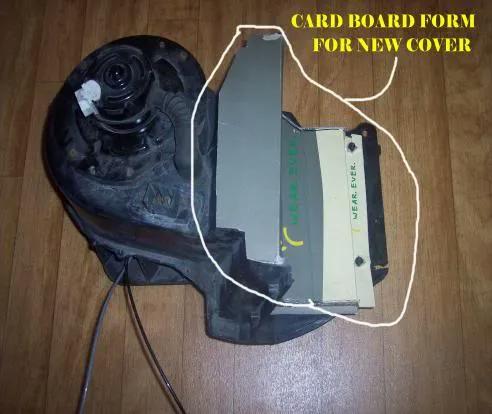
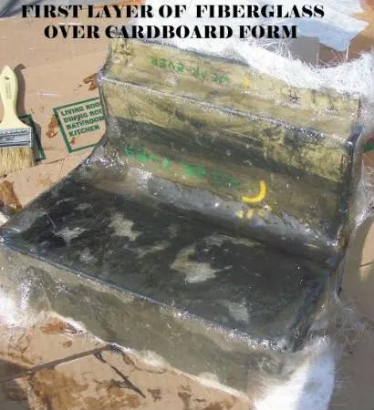
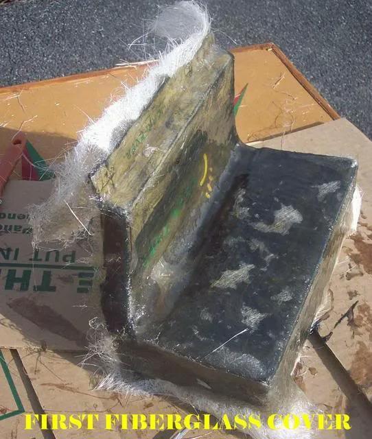
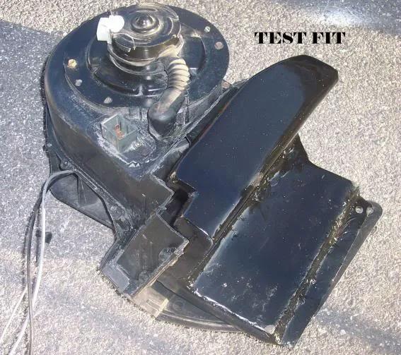
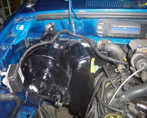
He removed the A/C coil and its cover, then made a cardboard pattern to establish the new shape needed for clearance. After test-fitting the pattern, he used it as a mold for fiberglass. The finished piece was shaped, cleaned up and fitted with its cover attached and sealed.
The modified heater box installed successfully. It cleared the inside corner of the 4.6L valve cover and left enough room to install the transmission dipstick.
The trade-off was that the Ranger no longer had functioning air conditioning. RJAAAAAA retained the original Ranger A/C equipment and refrigerant charge, but the evaporator was removed to obtain engine clearance. He considered the possibility of redesigning the blower box and relocating components in the future, but the completed installation documented here was a heater-box modification that retained heat, not a finished working A/C system.
A/C Compressor Pulley
Removing the A/C system from the cab did not mean the compressor could simply be removed from the engine and the original belt run without it. The 4.6L’s accessory drive needed a pulley in that location to maintain the belt path.
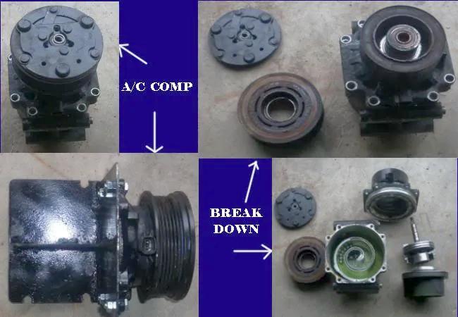
Rather than buying a commercial compressor-delete kit, RJAAAAAA made his own using the original compressor. He dismantled the compressor and reused its front flange, pulley and bearing. He fabricated a mounting bracket from 3/16-inch steel plate and installed the pulley assembly in the compressor’s original location.
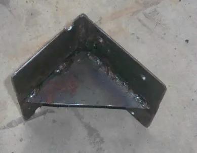
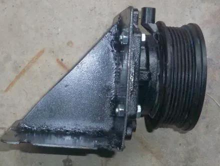
The bearing was approximately 1.25 inches in diameter and was supported by the flange rather than relying on the compressor shaft for support. The completed pulley kept the belt routed correctly and allowed the compressor body to be removed.
He later noted that the homemade pulley assembly fit well and that he had to move his remote oil filter to make room for it. The position of the remote filter therefore needs to be planned with the accessory drive installed, not treated as a separate job.
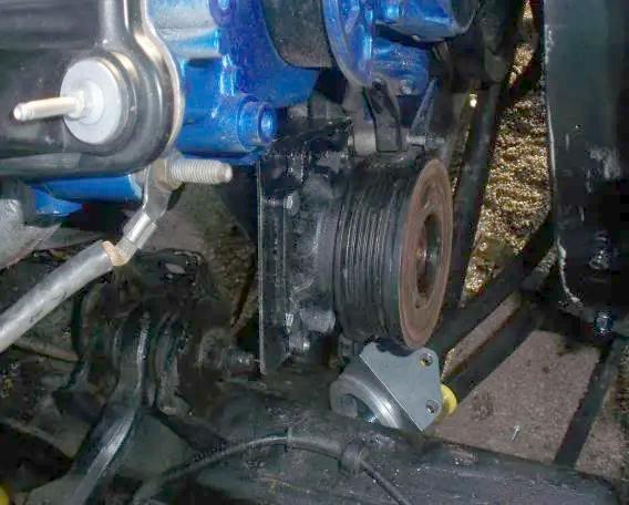
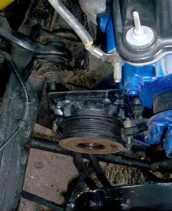
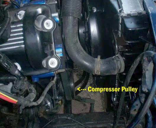
This modification kept the engine’s belt arrangement working, but it did not restore air conditioning. The compressor-delete pulley and the heater-box modification solved two different clearance issues.
Fuel System and Fuel-Line Routing
The original Ranger fuel-line connection was near the steering column, while the 4.6L fuel rail connection was at the front passenger side of the engine. The original line therefore did not simply connect to the new engine in its original location.
RJAAAAAA searched for the Ford fuel-line adapters needed to transition from the factory-style double O-ring fittings to AN-threaded fittings. He eventually ordered the adapters from Pace Performance.
For the connection to the fuel rail, he used braided fuel line routed behind the engine along the firewall. The first fitting he ordered had the wrong angle. He noted that the fuel-rail connection required a fitting with a 60-degree angle, or a 45-degree fitting would also work; the 150-degree fitting he initially purchased was not suitable.
The build also addressed the return line. The solution documented in the discussion used the original tank and sending unit, with a bulkhead fitting added to the top of the sending-unit assembly for the return. A steel return line was routed parallel to the supply line, and an OEM Mark VIII fuel-line section was used to connect to the rail.
He retained the original evaporative-emissions canisters rather than replacing the entire system with the donor car’s equipment.
These details matter because fuel plumbing is not just a matter of making the fittings connect. The lines must be securely routed away from exhaust heat, sharp edges and moving parts, and all fittings and connections must be rated for the fuel-system pressure.
Intake and Air-Filter Placement
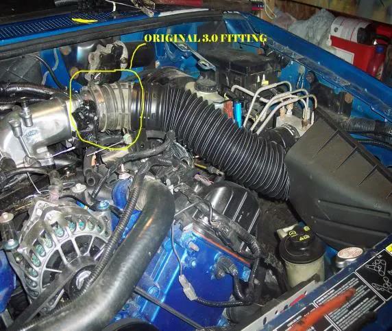
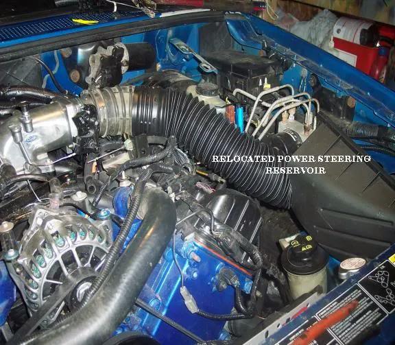
The Crown Victoria intake tube and air-filter box did not fit the Ranger’s engine compartment. The 4.6L throttle-body intake faced the driver’s side, but there was not enough room for the original air tube and filter box in that area.
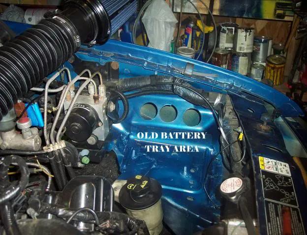
RJAAAAAA moved the battery to the front passenger side to free up space, but the Crown Victoria air tube still would not fit.
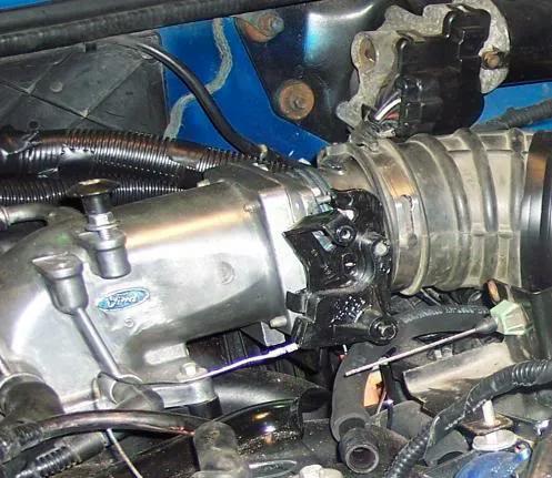
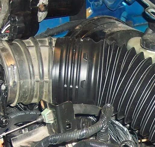
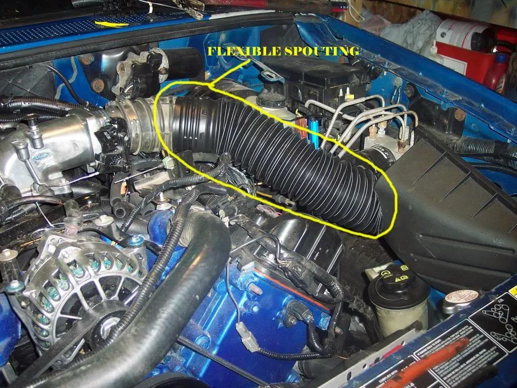
He used the original 3.0L Ranger intake snorkel’s throttle-body connector because its bend pointed the intake in a useful direction. The original snorkel was cut just beyond that bend and joined to a piece of 3-inch flexible drainage pipe purchased from a home-improvement store. The pipe expanded from approximately 12 to 24 inches and had an internal metal spring to help prevent it from collapsing. It fit tightly over the ribbed rubber connector at the throttle body.
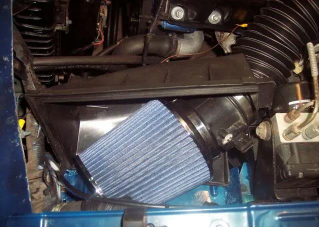
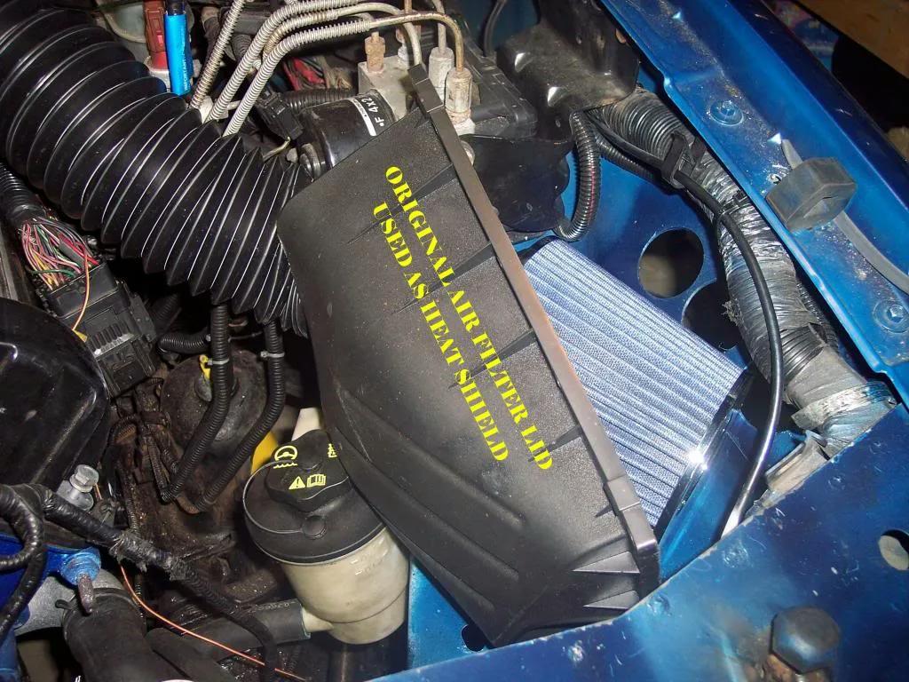
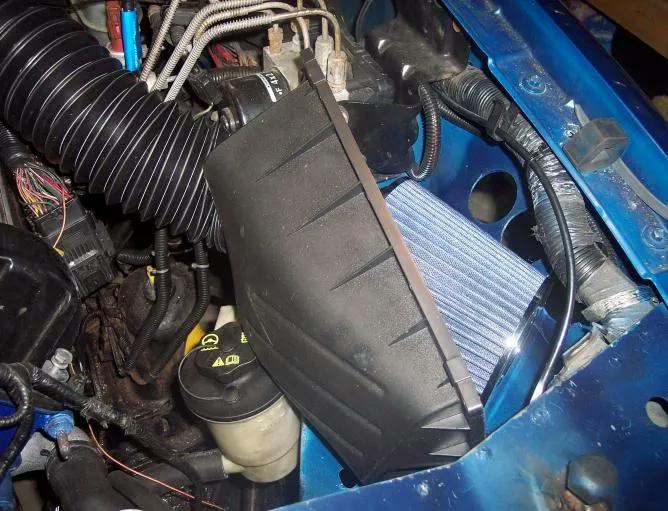
He then cut the mass-airflow sensor (MAF) out of the Crown Victoria’s plastic intake tubing, leaving enough material at each end to attach the new tubing and filter with hose clamps. A 3-inch Spectre conical air filter was fitted at the other end.
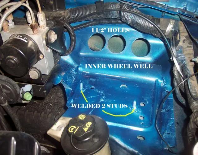
To admit cooler outside air, he cut three 1.5-inch holes in the inner wheel well. He added mounting studs for a shield and reused the top of the Crown Victoria’s plastic air-filter box as a heat shield behind the filter.
This was a home-built solution using available parts rather than an expensive aftermarket intake. The author noted that he was unsure how the flexible tubing would hold up underhood, so its long-term durability was not established in the thread. For a similar installation, make sure the intake tube cannot collapse under suction, loosen from the throttle body or contact hot or moving components.
Throttle Cable Linkage
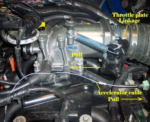
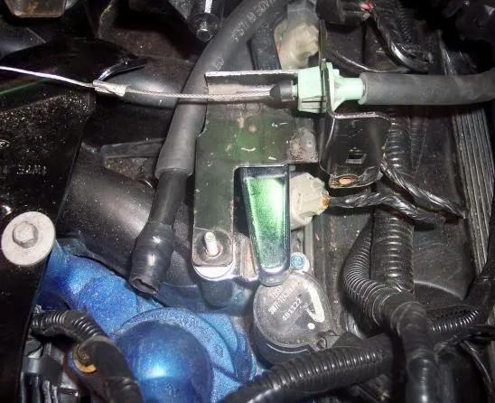
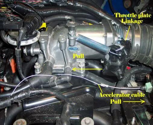
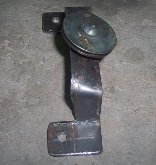
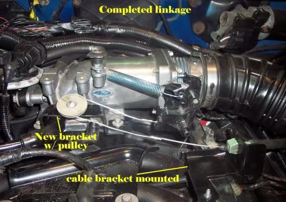
The accelerator cable and throttle-body lever pulled in opposite directions, so a direct connection would not work. RJAAAAAA fabricated a linkage to reverse the cable’s pull.
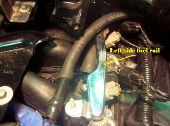
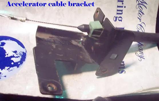
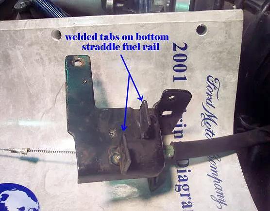
At the fuel rail, he adapted the original cable bracket. A stud was already available for mounting it; he welded a couple of tabs underneath the bracket so it straddled the left-side fuel rail and could be bolted into place.
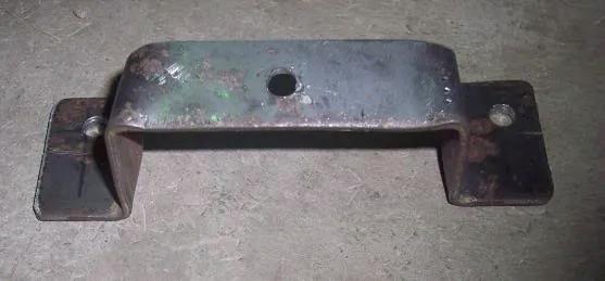
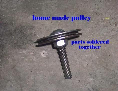
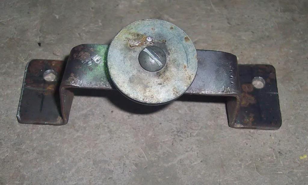
At the throttle body, he used the two throttle-body mounting bolts to attach a second bracket. This bracket held a small homemade pulley that redirected the cable pull.
The bracket was made from 1.5-inch-wide, 8-inch-long, 1/8-inch-thick flat stock, bent to fit the mounting location. The pulley was assembled from three 1/4-inch fender washers, with a flat washer in the middle, soldered together and mounted on a 1/4-inch bolt.
After test-fitting the assembly, he painted it and bolted it into place. He reported that the linkage worked smoothly and freely.
This is one of the more useful fabrication details in the build because it shows how he adapted the Ranger’s mechanical accelerator cable to the 4.6L throttle body. Any reproduction of the design must ensure that the throttle opens fully, returns positively to idle, cannot bind and remains secure through the engine’s movement.
Wiring, PATS and the First Start
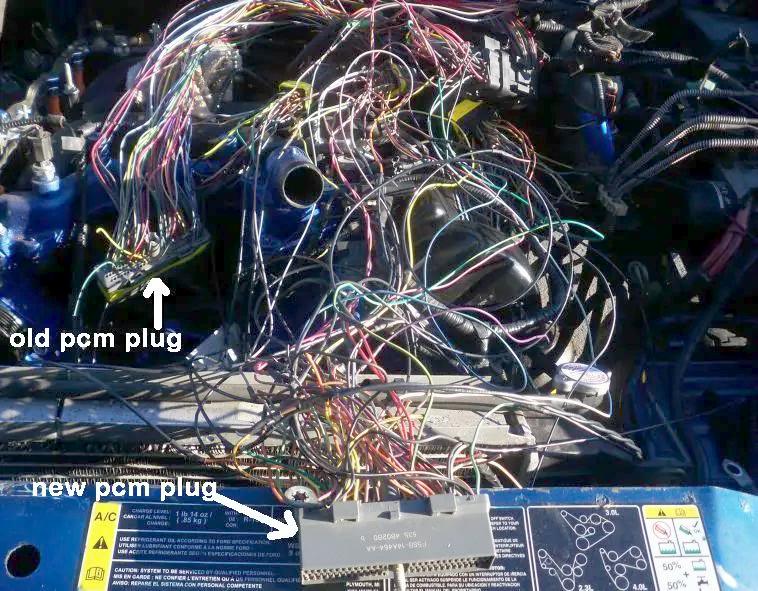
The engine swap used the PCM from the 2004 Crown Victoria Police Interceptor. The donor’s non-PATS configuration was important because the 2001 Ranger had its own factory PATS equipment.
When RJAAAAAA first connected the battery and tried to start the engine, the dash powered up but the engine did nothing. There was no starter operation and no fuel-pump sound. He initially suspected that the Ranger’s PATS system and the donor PCM were not communicating correctly.
He had already confirmed that he could make the engine crank by jumping the starter circuit at the PCM, so the next step was to determine why the PCM-controlled start sequence was not operating normally.
He traced the PATS transmitter wiring and disconnected the wires going to the PCM. But the no-start problem turned out not to be a PATS failure.
The fuel pump had been wired incorrectly. After correcting the pump wiring, he turned the key and heard the fuel pump come on. He then cranked the engine, and the 4.6L started.
This is an important lesson from the swap: a no-start condition after an engine conversion does not automatically mean the PCM or anti-theft system is the problem. Verify the wiring, power and grounds, starter control and fuel-pump circuit methodically before replacing parts or changing the engine-management system.
The P71 donor’s non-PATS setup should not be confused with the Ranger’s original PATS equipment. The fact that this particular police-car donor did not use a coded key did not eliminate the need to understand the Ranger’s wiring or to verify the final connections.
Summary of the Main Parts and Modifications
- Engine: 2004 Ford Crown Victoria Police Interceptor 4.6L SOHC V8.
- Engine mounting: Fabricated motor-mount plates; holes moved approximately 3/4 inch forward; engine positioned approximately 1.5 inches to the passenger side of the original engine position.
- Clearance work: Passenger-side shock-tower modification and filler plate; upper control-arm bracket trimming; frame rail moved inward approximately 1/4 inch; 1/2-inch motor-mount shims for exhaust-manifold clearance.
- Transmission mount: Fabricated bolt-on plate to bridge an approximately 1-inch gap to the original rear crossmember.
- Oil filter: Non-P71 filter adapter from a salvage yard, with a Trans-Dapt 1127 remote-filter kit and Trans-Dapt 1427 90-degree bypass adapter.
- Radiator: Four-core aluminum radiator from a 1999 Mercury Mountaineer 4.0L.
- Cooling fan: Crown Victoria electric fan adapted to the original Ranger 3.0L shroud.
- Radiator position: Approximately 2 inches forward and 2 inches down; lower radiator support modified and extended.
- A/C compressor drive: Homemade delete-pulley bracket using the original compressor’s front flange, pulley and bearing, mounted with a 3/16-inch steel bracket.
- Heater box: A/C evaporator removed; custom fiberglass section made from a cardboard pattern to clear the passenger-side valve cover while retaining heat.
- Fuel lines: Ford EFI-to-AN adapters, braided line to the fuel rail, and a return line added to the original sending-unit assembly.
- Intake: Modified Ranger intake connector, 3-inch flexible tubing, Crown Victoria MAF sensor, Spectre 3-inch conical filter and a modified heat shield.
- Throttle linkage: Modified Ranger cable bracket and a fabricated cable-reversing pulley bracket.
- Engine management: 2004 Crown Victoria P71 PCM; initial no-start traced to incorrectly wired fuel pump, not a failed PCM or PATS system.
Additional Build Documentation
The forum discussions contain photographs that are especially useful for the fabrication work described above. They should be consulted alongside this article for the original views of the motor mounts, frame and control-arm clearance, radiator and fan assembly, oil-filter adapter, modified heater box, intake and throttle linkage.
- Project OUTRANGEROUS update: https://www.therangerstation.com/forums/threads/project-outrangerous-update.116000/
- New member / new engine swap: https://www.therangerstation.com/forums/threads/new-member-new-engine-swap.114503/
- Let the swap begin — 3.0 to 4.6: https://www.therangerstation.com/forums/threads/let-the-swap-begin-3-0-to-4-6.114673/
- Oil filter relocation: https://www.therangerstation.com/forums/threads/oil-filter-relocation.115090/
- Project OUTRANGEROUS 4.6L Install / Phase 2: https://www.therangerstation.com/forums/threads/project-outrangerous-4-6l-install-phase-2.116900/
Related Articles
Got302ci’s 4.6L SOHC swap article
About The Author
Jim Oaks is the founder of TheRangerStation.com, the longest-running Ford Ranger resource online since 1999. With over 25 years of hands-on experience building and modifying Ford Rangers — including magazine-featured builds like Project Transformer — Jim has become one of the most trusted authorities in the Ford Ranger off-road and enthusiast space.
Since launching TheRangerStation.com, Jim has documented thousands of real-world Ranger builds, technical repairs, drivetrain swaps, suspension modifications, and off-road adventures contributed by owners worldwide. TheRangerStation.com has been referenced in print, video and online by enthusiasts, mechanics, and off-road builders looking for practical, and experience-based information.