
Introduction
One of the hottest trends on serious off-road rigs now is triangulated 4-link suspensions. I too have fallen victim to the desire to build my own 4-link and began doing research on how to design and construct one. I’ve looked through many resources and pulled out what I felt was the best pieces of information and put it all together in this article. The first two sections are on measuring and building your own 4-link. These articles are all over the internet and were written by Fred Williams at 4Wheel & Off-Road Magazine (www.4wheeloffroad.com). I’ve seen a lot of good tech on the net come and go over the years, so I’ve preserved his articles here to ensure they’re not lost.
Article Contents:
Measuring Strength Of Materials
Four-Link Tech – Part 1 What Is A 4-Link? And Is It For You?
By Fred Williams at 4Wheeloffroad Magazine
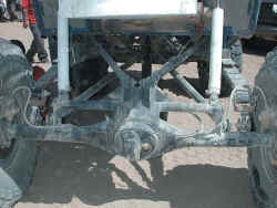
A four-link suspension uses links to locate the axle from moving side to side and front to back, while allowing it to travel up and down and articulate. We must agree with the current majority that a four-link suspension with coils, coil overs, quarter-elliptics, or air springs is definitely cool, and that is the most common argument for building your own setup. The problem arises when you think you know what you are doing and just start putting bars and links under your truck. Just because you saw it on some race truck or rock crawler doesn’t mean you need it for your weekend wheeler, though we have no problem with building one just because you want to try it.
There are some definite benefits to running a four-link, but to do it right takes time, money, and some more time and money. We hope to give you a realistic overview of a simple rear four-link suspension, but first, the pros and cons of building one. The choice is yours, but please consider everything before you get started. The fact remains that a well designed and tested four-link will provide a superior translation of power to the ground and higher ride quality than a leaf-sprung suspension. The secret is really in the testing portion. If you build a four-link on your rig then be prepared to fine-tune it and tear it apart quite a few times before it works right. And during this testing stage we would not recommend driving it to work on the highway at 60 mph. You may get lucky the first time, but if not, remember that tearing your truck apart and re-building it is fun.
Considerations
The biggest question with building a four-link is how long should the links be and where should they attach to the frame and axle. This alone will determine how the axle pushes the vehicle, if the rear of the vehicle lifts or squats under acceleration, if wheel articulation causes the rear axle to pivot and steer, and how the body rolls in turns and over obstacles. The desired amount the vehicle does each of these things is different depending on what the vehicle is designed to do (go fast, corner, crawl, articulate) and how the driver desires the vehicle to respond on different terrain. There is no one right way to build a four-link the same as there is no one perfect off-road vehicle, but it can be tuned to do certain things better than others.
For most truck owners an all-around four-link is the desire, but that will not necessarily be the best rock crawler, desert jumper, and mud bogger suspension. In addition to all the geometry of designing a four-link there is also the problem of what will actually fit on the vehicle you are building. Will the frame support the links where you want them? Will the fuel tank, exhaust, crossmembers, and driveshafts all fit with the links and allow for proper articulation? Unless you are building a truck or buggy around the suspension, plan on doing some compromising to get the best setup you can. If you are starting to like the idea of keeping
the leaf-spring suspension, we don’t blame you. If you are up for the challenge, stay tuned for next month where we start getting into the technical part of the buildup.
Till then you have a bit of homework. You’ll need to round up a tape measure, a calculator, graph paper, and a pencil. Now go measure your wheelbase and decide on the height of the tires you want to run on your rig. Follow that by measuring the rear axle width just inboard of the brake-mounting plates and the height of the frame at various points between the axles along the frame rails while the truck is on level ground. Next find the height of the top center bolt of your bellhousing to the ground. Plus, start doing research of where you can buy the materials we mentioned below. Just remember you will want to wait until
you have read the second part of this story next month before you attack the four-link issue under your truck.
The benefits of a four-link over a simple leaf-spring suspension include controlling axle wrap, better departure angles, controlling axle path, and reducing the uncontrolled variables of axle movement down to just spring rate and shock valving. In addition, a four-link can also allow for more travel and articulation that can provide more traction, though we feel that too much of both can cause problems. Weight is also a concern of the modern-day wheeler since excessive weight eats power. Though a coil spring is lighter than a leaf spring, when you consider the weight of the links and mounts and everything else, the gains in
weight are minimal.
The major benefit of a leaf-spring suspension over a four-link is cost and maintenance. It will take more time and money to remove leaf springs and design, build, test, and rebuild your four-link than it would to just put on a good leaf suspension, and this is if you do it yourself. With shop rates ranging from $25 to $75 per hour, a professionally fabricated four-link is gonna take a serious bite out of your wallet. Plus we have seen some very impressive leaf-sprung suspensions that allow plenty of travel and articulation.
Material is an important factor and concern for strength and safety. Your lower links could be hitting trail obstacles depending on how low you mount them to the axle, so we would recommend no less than 1 3/4-inch DOM tubing with 0.25-inch wall thickness. If your truck is a full-size or extremely heavy, or if you are planning on mounting your shocks on the lower arms like some race trucks, then you will want to go to an even larger tubing size, or better yet, sleave the 1 3/4 x 0.25 with a slightly larger piece of tube. The upper links are less likely to be hit by rocks and such, but we still do not recommend anything less than 0.120 wall, 1 3/4-inch DOM tubing.
As for the joints at the ends of the links, get the best you can afford. The links will last longer and be stronger if you spend the extra dimes, plus if they fail it can be tragic. Everything from Johnny Joints to Heims are applicable. Many Companies like Poly Performance and Avalanche Engineering can supply you with these joints and the proper weld-in bungs to screw them into the links. And remember that the mounting bolts should be as close to perpendicular to the link as possible when installed at ride height to get the maximum strength from the joints.
For the mounts we will steer you toward 0.25-inch-or-larger material. Many shops like A&A Manufacturing, McKenzies Performance Products, and circle-track race shops offer tabs and brackets that can be welded to frames for link mounts if you don’t have the facilities or tools to cut and build your own. As for the axle
mounts, your upper-link mount will most likely be a bracket that bridges over your differential housing. Welding directly to the cast housing is tricky and if you don’t know how then plan on building a bridge out of 0.188 wall 1 3/4-inch or larger DOM or square tubing.
Grade 8 hardware is the best bet for attaching all the links to the brackets and should be at least 7/16 inch if not larger. Remember when you have everything together that, like everything else on your off-road machine, you should check for loose or broken parts before trail runs.
Four-Link Tech – Part 2 The Nitty Gritty Confusion of Four-link Suspensions
By Fred Williams at 4Wheeloffroad Magazine
Last month we started an in-depth look at the benefits and detriments of a four-link suspension. We touched on how a four-link will reduce the number of variables down to just the spring rate and shock valving. In addition, a four-link is expensive to do right, and this second installment will hopefully take you from the drawing board to the garage floor.
There are many different link configuration possibilities, but for this discussion we’ll stick to a basic four-link where the upper two links start at the frame and converge at the top center of the rear axle. The lower two links will also run from the frame to the outer ends of the axle tubes. A three-link is similar, but the upper links are replaced by an A-arm with a single joint at the top of the axle. The three-link setup puts that upper axle joint under greater side loads than the upper two links of a four-link, but it is a viable alternative. Also, suspension builders will argue till the cows come home about what works best, but what we have done is discuss with some of the top desert-race suspension builders how to get you started on a four-link. This design is just a launching pad, and you will need to spend a fair bit of time dialing everything in. In addition, there are many excellent books available to learn more about suspension design. We would recommend:
Chassis Engineering – by Herb Adams
Fundamentals of Vehicle Dynamics – by Thomas D. Gillespie
Race Car Vehicle Dynamics – by Milliken and Milliken.
Though some of these books are pretty heavy, they do help explain the theories behind four-link suspensions, but mostly when applied to street cars and not off-road vehicles. To truly explain a four-link, we would need this entire magazine and a few engineering degrees, and even then, there would be things that would be missed. This, however, should be enough to get you started. Just take your time and enjoy the process, because if you don’t have the patience to adjust and rebuild your suspension until it works just right, then you should stick to leaf springs.
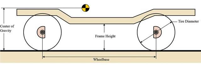
The first step in building a four-link involves a tape measure and some graph paper. What you are going to do is figure out the angle of the links and their mounting locations. This will in turn give you an idea of where to start building your four-link. From there you can fine-tune it. Park the truck on flat ground and measure your wheelbase and the tire size you will be running. Plot the axle centerline points on the bottom half of the graph paper as if you were looking at the side of the truck. Now draw the frame rail as it sits above the axle centerlines. This should be where you expect the frame to sit above the axle if you have not yet lifted it. If you know the height and location of your center of gravity of the sprung weight, plot that as well. If not, estimate it by measuring from the top center bolt of the bellhousing to the ground. You may need to add the height of the expected lift if the truck is still stock.
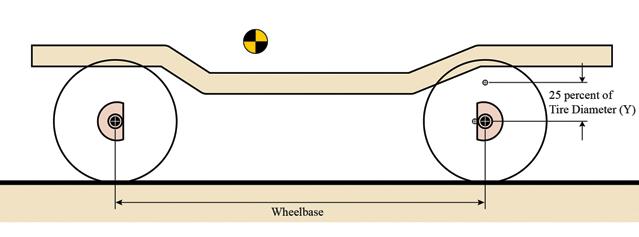
Now plot a point on the front center of the rear axle tube. This will be your lower link mount. Some people mount this above or below the axle tube, but we have found that the important part is more the difference in height from the upper-link mount. If your truck is going to be very tall, you may want to put these links on the top of the axle tube. To find the upper-link axle-mount point, multiply the tire diameter by 0.25 (25 percent). Use that number as the distance in inches that the upper link will be above the lower link at the axle. If you were running 36-inch tires, you would want the upper links to be mounted 9 inches above the lower-link mount. You will most likely be mounting the links 8 to 11 inches apart. The farther apart you can get them right now, the better, as this will help control the leverage of the tires and fight axle wrap. The limiting factor will most likely be the bed of the truck. Continue by plotting the upper- and lower-link axle-mount points. If this is getting confusing, then you are normal; if it’s clear as a bell, you may be a bit too smart for your own good.
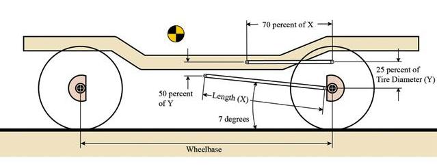
Since you have a rough idea of where your axle-mounting points will be, it’s time to move onto the frame mounts. The first point to plot is the lower-link frame mount. To determine this, draw a link with a 5-to-10-degree angle up from the axle mount to the frame in the sideview drawing. Watch where the link intersects with the frame; this point will most likely be near the transfer-case rear output. It should also be as high as possible for ground clearance, but low on the frame to keep the link as level as possible. If you cannot get the link to intersect the frame at 5 to 10 degrees, you may need to move the lower-link axle mount up on the axle tube. If so, you will also need to move the upper-link axle mount as well to keep the predetermined 8- to 11-inch vertical spacing between the links at the axle.
Another option is to consider building a crossmember mount below the frame rails. At this point you should be realizing that a four-link involves tons of variables and compromises, and we haven’t even gotten to actually looking under the truck yet! Now take the horizontal distance from the lower-link frame mount to the lower-link axle mount and multiply that number by 0.7 (70 percent). This is a good horizontal length of the upper links. The distance apart that you mount the upper and lower links on the frame should be about half the vertical distance apart of the link’s axle mounts. Again, try to keep the links as level as possible.
Start looking at the width of the frame at the point where the upper links attach and write this measurement down. Subsequently measure the distance along the axle tube from just shy of one brake mounting plate to the other. This will be the distance apart of your lower-link axle-mounting points. If at this point you are starting to really like the idea of leaf springs, then we congratulate you for having some common sense. If you are still thinking that you’ll be the talk of the town with your new super four-link suspension, then dig out that piece of graph paper and sharpen your pencil, because there is more work to
do.
If you have a pile of graph paper crumpled into balls and a headache from thinking too hard, then you are right on track. The tricky part comes when you take your drawing and see if you can actually attach the links you drew on the truck’s frame and axles. This is where compromise comes in. You may need to move the fuel tank, exhaust, or various other low-hanging parts of your truck. There is always a bit of adjustment available. The upper links can be slightly longer or shorter than 0.7 (70 percent) of the lower links, but try not to pass 0.6 (60 percent) or 0.8 (80 percent).
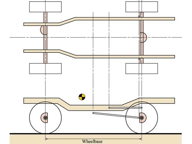
On the graph paper draw lines up to the top of the paper from the front- and rear-axle centerline, upper- and lower-link axle, and frame-mounting points. Next, in the upper space draw the rear axle from the top view with the lower-link axle mounts plotted at the distance apart you measured from the actual rear axle. Follow that by drawing in the frame rails from the top view with the center of the frame over the center of the rear axle. But wait, there’s more.
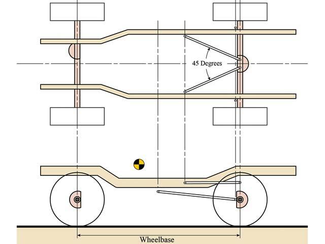
Draw in the upper links first. Remember to have them start from the frame, but at the axle keep them slightly separate to allow access to the nuts that will go on the ends of the bolts running through your rod ends. Now grab an angle finder. It is very important that the angle of the two upper links be no less than 40 degrees. This angle is what locates the axle laterally or side to side. The smaller or shallower the angle, the weaker the lateral control. This again may mean shortening the upper links but try not to make them less than 70 percent of the horizontal length of the lower links. If need be, you may need to shorten the lower link’s horizontal length as well but try to keep them as long and as level as possible. If you are wondering when you get to start installing your really cool new coil over shocks, then you might need a lesson in patience. Get another cup of java and keep studying.
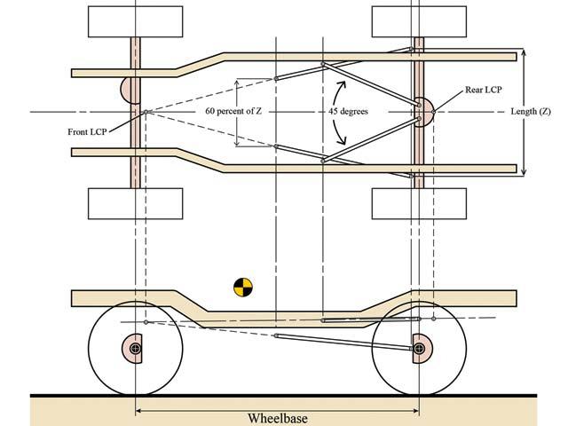
To reduce the rear steer of the axle, we need the tire to move towards the center of the frame, side to side, as it articulates and not towards the center of the frame, front to back. First you need to draw in lines extending from the links until they converge when viewed from the top of the vehicle. These convergence points are known as the lateral constraint points (LCP). The upper-link’s extended lines will most likely converge at an LCP just behind the rear axle. The lower-link’s extended lines should converge at an LCP somewhere forward of the transmission, depending on how much of an angle you give them when looking at the top view. An angled set of lower links helps the upper links locate the axle laterally and fight rear steer but also requires a larger area to slide over obstacles. The best route seems to be a slight angle, but not as severe as the upper links. An acceptable angle will have the lower link’s separation at the frame equal to 50 to 70 percent of axle-mount separation, which may require fabricating a crossmember to mount them to, as discussed earlier.
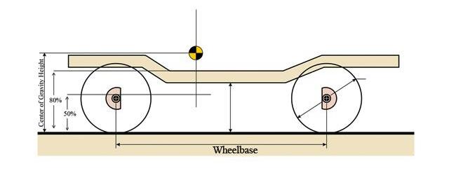
Moving on, take your center of gravity height measurement and multiply it by 0.5 (50 percent) and write down your answer. Now multiply the height by 0.8 (80 percent) and write that down. Next, draw a vertical line through the front axle perpendicular to the ground, and plot two points using your answers above as the number of inches from the ground. The space between these two points represents the percent of anti-squat you will be aiming for. This will be discussed further in Figure 9.
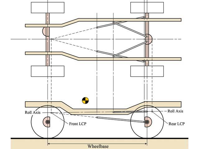
Next draw a vertical line down from the LCPs to the sideview drawing. Extend lines from the upper links back and lower links forward until they cross
the lines you brought down from the LCPs. This will show you the heights of the LCPs. Now when you connect the two LCPs on the lower drawing with a straight line, you will get the roll axis. This is the imaginary line perpendicular to which the axle will articulate. As such, you want the front of the roll axis slightly lower than the rear. This will give better handling, and less rear oversteer as the axle articulates. If your roll axis leans toward the back of the truck, you may need to lower the upper link’s frame mount or increase the height of the axle bridge. Just don’t let the upper link’s frame-mounting point get lower than the lower-link’s frame-mounting point—better yet, keep them apart. As you can see, there will be many opportunities to adjust and diverge from the original design to get the geometry correct.
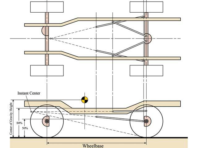
To make sure your suspension transmits power to the ground, you want a certain amount of anti-squat. This will let the tires move the vehicle forward without the energy compressing or expanding the suspension. The perfect amount of anti-squat is debatable, depending on the driver’s desires. Some want the vehicle to crouch when accelerating, but this is sending the power into the springs. Some want the vehicle to lift under acceleration to gain more traction, but this can let the axle walk under the vehicle instead of propelling it forward. We will try to design the suspension not to squat or lift excessively, while erring on the squat side. The way to determine anti-squat is to run a line from the contact patch (CP), or center of where the rear tire touches the ground, to a point where the upper and lower links would converge in the front of the vehicle while viewed from the side.
The point towards the front of the vehicle where the links would converge is known as the instant center (IC). The line from the instant center to the contact patch of the rear tire should run across the vertical line through the front tire. If it is within the 50 percent to 80 percent of the center of gravity height at the front tire that we determined in Figure 7, then it should be a good amount of anti-squat to start from. If you want it to lift more, you need the line to be closer to the center of gravity or above 80 percent. If you want it to squat more, you want the line closer to the ground or below 50 percent. Now if the anti-squat is not where you want it, you must start adjusting the link-mounting points. If you move the lower axle point up on the axle, remember to raise the upper link’s axle mount as well. If you move the lower link’s frame mount, then you may need to move the upper link’s frame mount as well. Then after you think you have gotten the links where you want them, move your new dimensions back to those of Figure 8 and make sure your roll axis is angled towards the front of the truck. Expect to spend many long hours moving your measurements back and forth between Figures 8 and 9 until you have everything dialed in.
Once you have all this figured out, it’s time to start on the truck. Begin by building your axle bridge to mount the upper links to the axle and the lower link’s axle mounts as well. Remember to set your pinion angle first, depending on whether you will be running a CV or U-joint, and then only tack-weld everything. If you need to change it, this will make moving parts that much easier.
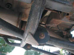
Next, build the bracket to attach the lower links to the frame. You may want to build a crossmember for this if you determined that you need it to get a better roll axis. These brackets may also become skid points when you encounter obstacles, so you might want to build their forward edge with an angle to help slide over things.
Just be sure to use the proper materials we discussed last month, as there is a fair bit of force put on all of these points. Plus, if you are not a skilled welder, or this is your first welding project, stop right now. The welds on these components must be very good; if they fail, it can be fatal.
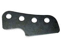
When you get to the upper link’s frame mount, we recommend using a bracket that has multiple holes drilled for attaching the upper links such as this one from A&A Manufacturing. Attach this bracket so you can move the upper link’s frame mounts up and down from the ground. This will be your initial point of adjustment to fine-tune the suspension whether you are going racing or rock crawling.
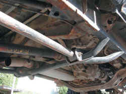
Now that you have everything in place, it is time to cycle the suspension. Notice if the axle moves straight up and down as it should or if it swings forward as it articulates, as it shouldn’t. Are the links and rod ends binding? If so, do the brackets need to be angled to follow the line of the links? Plus, what about everything under the truck—exhaust, fuel tank, spare tire, and so on? Is there clearance
for these or do they need to be moved? If everything seems to be right, it’s time to burn in the welds. Just remember that it is not uncommon to need to tear into the suspension again to get it to work a bit better. Do not be surprised if you are adjusting things three or four times before you get it how you like it. You may still want to change more, depending on the terrain you encounter or the driving style you prefer. This is only one way to build a four-link, and different builders will try different methods. If you enjoy a challenge and are willing to spend the time, money, and energy to fine-tune your suspension, then a four-link may be right for you. If not, then stick to a professional kit, or leaf springs, and just go have fun on the trail.
Going Further…………….
I have taken the 4-link Tech articles and added the following sections……
Monster Trucks & 4-Links
I know what you’re thinking, I’m not building a monster truck. I’m climbing rocks. I thought it would be interesting to see what the monster trucks guys were doing and what materials they were using. The oldest and original monster truck is Bigfoot.
When Bob Chandler, the creator of Bigfoot, decided to upgrade from 2-ton truck frames and leaf springs he wanted a truck that would be safer and faster than previous builds. At the time, monster trucks were starting to weigh in at as much as 15,000 pounds. 5,000 pounds
more than today’s monster truck. To build safer, faster vehicles, he looked relentlessly for materials that had optimum properties, such
as strength and rigidity. These materials also had to be low in weight. One of these materials was tube.
For the frame, Chandler collaborated with Dan Patrick, who had experience designing dragsters. Chandler spent nearly 800 hours using a CAD program to design and refine the tubular structure. The frame was built from welded drawn-over-mandrel (DOM) mild steel tubing and assembled with gas metal arc welding (GMAW) and heliarc welding.
“We use DOM tubing because it’s stronger and more uniform in diameter than as-welded tube,” said Jim Kramer, vice president of operations of the company. “That allows us to take a short length of a smaller-diameter tube and slide it into another and plug-weld it.
We do that usually where we need extra strength, such as where two tubes come together. This double wall allows us to make a stronger joint, both when building and repairing a frame.
“We do a little bit of heliarc welding too,” Kramer said, “in areas that need a cooler weld, or where we have a difficult-to-reach spot that we can’t get to with the other welding unit.”
As for suspension links, “We use 1/4-in. chrome-moly tubes to make the four link bars, which are used to locate the axles,” said Kramer.
“We have them heat-treated in a salt brine. These tubes flex an awful lot. You’d never see it because it happens so fast, but they flex
quite a bit. Heat treating raises its yield point, allowing the material to flex more without a permanent change to its shape. In other words, heat treating expands the tube’s memory, so it flexes further and can still remember where it came from,” Kramer explained.
BIGFOOT monster trucks use a mixture of steel and chromium-molybdenum tube. The frame and cage are 2-in.-OD, 0.120-in.-wall ASTM specification 1020 DOM tube, The four link bars are 2 1/2-in.-OD, 0.250-in.-wall 4130 chromium-molybdenum tube, with tensile strength of 162 to 194 KSI and yield strength of 123 to 159 KSI.
Equal Length VS Unequal Length Links:
I don’t want to throw a wrench in to things and contradict the 4Wheeloffroad article above about using shorter upper links, but I think this is worth looking at…..
With the early 4-links in monster trucks, most designs utilized unequal (shorter upper) link bars and to allow for more lateral angle due
to the narrower chassis in use at the time.
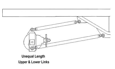
Shorter upper links provided more lateral angularity and kept them clear of important components.
This was not a problem until considerably longer travel suspensions were employed. This eventually became a problem due to the differences in deflection rates of the upper and lower links. This often made for undesirable pinion angle changes as well as ‘Caster’ changes which also adversely effect stability.
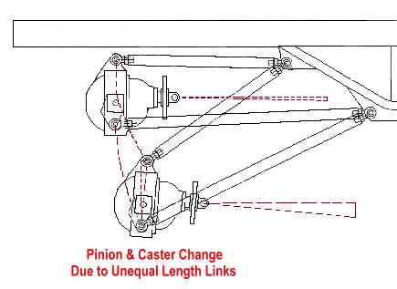
Note that as the suspension cycles the shorter upper links deflect more than the longer lowers. This in turn makes for changes in caster and pinion angle.
Eventually wider chassis designs incorporated equal length links which eliminated these problems.
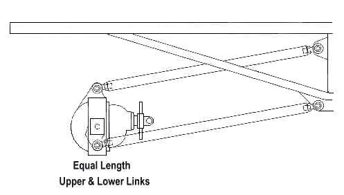
Equal length upper and lower links deflect equally and do not effect caster or pinion angle as long as they are vertically parallel to each other.
If you use Triaged’s 4 Bar Link Calculator V3.1 below, it will let you cycle the suspension and calculate the pinion changes.
For more information on the evolution of monster truck suspensions, click HERE.
Strength of Tubing Materials
Material Selection:
provide plenty of strength, will be cost effective to work with and that you will be able to work with now and in the future. For example, chromoly requires tig welding? Will you have access to tig welding now and in the future if something needs replaced?
Carbon Content:
Steel is produced from iron and carbon. Iron alone is generally soft and weak. It is the addition of carbon that gives the steel its
strength. The carbon content is displayed in the materials AISI number (Example 1026 DOM). A 1026 carbon steel is going to be stronger than a 1020, 1018, etc.
AISI (American Iron and Steel Institute) Designations (The 4-Digit Numbers):
Carbon steels and low alloy steels are designated by a four-digit number, where the first two digits indicate the alloying elements and the last two digits indicate the amount of carbon, in hundredths of a percent by weight. For example, a 1060 steel is a plain carbon steel containing 0.60 wt% C.
| Carbon Steels | |
| 10xx | Plain Carbon (Mn 1.00% max) |
| 11xx | Resulfurized |
| 12xx | Resulfurized and Rephosphorized |
| 15xx | Plain Carbon (Mn 1.00% to 1.65%) |
| Manganese Steels | |
| 13xx | Mn 1.75% |
| Nickel Steels | |
| 23xx | Ni 3.50% |
| 25xx | Ni 5.00% |
| Nickel-Chromium Steels | |
| 31xx | Ni 1.25%, Cr 0.65% or 0.80% |
| 32xx | Ni 1.25%, Cr 1.07% |
| 33xx | Ni 3.50%, Cr 1.50% or 1.57% |
| 34xx | Ni 3.00%, Cr 0.77% |
| Molybdenum Steels | |
| 40xx | Mo 0.20% or 0.25% |
| 44xx | Mo 0.40% or 0.52% |
| Chromium-Molybdenum (Chromoly) Steels | |
| 41xx | Cr 0.50% or 0.80% or 0.95%, Mo 0.12% or 0.20% or 0.25% or 0.30% |
| Nickel-Chromium-Molybdenum Steels | |
| 43xx | Ni 1.82%, Cr 0.50% or 0.80%, Mo 0.25% |
If a letter L or B shows up between the second and third digits of an AISI number, it means that this grade is either a Leaded steel or a Boron steel; Sometimes a suffix H is attached to a AISI number to indicate that the steel has been produced to prescribed hardenability limits.
PSI Ratings –
I found various psi ratings for tubing on line. Ask your supplier for material certificates to get their tubing’s yield strength.
A-53 Pipe – Schedule 40 & Schedule 80 Extra Heavy Pipe-
A-53 pipe should never be used in suspensions. ASTM A-53 is intended for mechanical and low pressure applications and is also acceptable for ordinary uses in steam, water, gas, and air lines. Yes, we’ve seen people use pipe for everything from bumpers to roll cages on their
off-road rig because their cheap and they can get it at the hardware store. Pipe has a low carbon content and should be avoided.
A-53 has a yield strength of 30,000psi
Electric Resistance Welded (ERW) Tube –
ERW (Electric Resistance Welded) – Cold formed, electric resistance welded tubing can be produced in round, square or rectangle shapes. ERW tube is produced by processing a flat rolled steel into strips which are cold-formed, welded and seam annealed or normalized (depending on the manufacturer). You can usually identify ERW tube by the blue strip down one side of the tube (which is the welded area). The ERW process can guarantee the weld to be as strong or stronger than the rest of the tube body. ERW can also be known as CREW (Cold Rolled Electric Welded).
ERW has a yield strength of 32,000psi
HREW (Hot Rolled Electric Welded) – HREW is steel that is rolled to size in the mill while red hot. Hot rolling steel does not work harden it as much as cold rolling. For this reason, hot rolled steel is more easily machined than cold rolled.
HREW has a yield strength of 40,000psi
CREW (Cold Rolled Electric Welded) – CREW are steels that are shaped by high pressure rollers at normal temperature in the steel mill. Cold rolling work hardens the material substantially. The steel is then welded by the electric weld process. A cold rolled steel can be either a mild steel or a high carbon steel. It can also be termed as ERW (Electric Resistance Welded).
CREW has a yield strength of 45,000psi
DOM-
DOM (Drawn Over Mandrel) – is the most commonly used material for suspension links. DOM is formed from strip and Electric Resistance Welded (ERW) tube that undergoes a caustic wash and is annealed in a furnace to add strength to the steel. It is cold drawn through a die and over a mandrel resulting in a uniform wall thickness. Because of this extra work it has a higher yield strength than ERW and of course a higher price.
1020 DOM has a yield strength of 50,000-60,000psi.
1026 DOM has a yield strength of 60,000-70,000psi.
There seems to be some variance in what different company’s are rating their DOM yield strength at. Ask your supplier for material certificates to get the tubing’s yield strength.
Aluminum –
Aluminum isn’t commonly used but has some interesting qualities and is gaining popularity. If you choose aluminum, you’ll want 7075-T6. It’s used extensively in the aircraft industry for its high strength and light weight. It is much lighter than DOM and has a higher yield strength. Aluminum is more flexible and would be more prone to buckling than the same size DOM. Aluminum links would have to be made from solid material and the ends would have to be drilled and tapped for installing rod ends.
Make SURE it’s 7075-T6.
7075-T6 has a yield strength of 73,000psi
7075 only has a yield strength of 14,000psi. Make sure it’s T6.
6061-T6 only has a yield strength of 40,000psi.
You can buy 7075-T6 aluminum links with joints attached from http://www.summitmachine.com
Things to consider – you’re not going to be able to weld aluminum in the field as a temporary fix like you can steel.
Chromoly –
Chromoly is an abbreviation for “chromium-molybdenum steel”. It is not as lightweight as some steel alloys, but has the advantages of high tensile strength – 90,000-95,000psi in the normalized condition – and malleability. It is also easily welded and is considerably stronger and more durable than standard (1020) steel tubing.
Chromoly is often called “4130” because the carbon content is nominally 0.30%. With this relatively low carbon content the alloy is excellent from the standpoint of fusion welding.
The alloy can be hardened by heat treatment or “normalizing”. This is a process of taking 4130 tube up to a prescribed temperature and cooling it at a precise rate. This removes all strain created in the tube manufacturing process and allows the homogenization of the steel’s grain structure.
4130 Steel, normalized at 1600°F, air cooled has a yield strength of 60,200psi
4130 Steel, cold worked & normalized has a yield strength of 75,000psi
4130 Steel, water quenched 1570°F, 1100°F temper has a yield strength of 92,100psi
4130 Steel, water quenched 1570°F, 1000°F temper has a yield strength of 99,400psi
4130 Steel, water quenched 1570°F, 900°F temper has a yield strength of 110,000psi
Good luck with this stuff. While searching the internet for yield strength ratings for 4130 chromoly I found all kinds of ratings. Many forums and sites will list normalized at 75,000psi, but it’s hard to find a company listing it at that rating. AED Motorsports Products was the only one I found.
Ask your supplier for material certificates to get the tubing’s true yield strength.
Things to consider – Chromoly is more expensive than DOM tubing. To get the full strength of chromoly it has to be heat treated after all end machining and welding. In addition, if you choose to weld threaded inserts into the tubing it must be tig welded for maximum strength otherwise you might as well use DOM. You may be able to save up the cash for chromoly now, but if you have to replace a link later will you be able to afford it and still have the means to get it tig welded?
Material Recommendation
1020 – 1026 DOM tubing is probably your best option for building your links due to its availability in most areas, strength and affordable price. It also doesn’t have the stricter welding requirements of chromoly.
Chromoly would be idea if you had a healthy wallet and an endless means of tig welding.
Aluminum would lighten up your rig but can’t be field repaired. Order your links from http://www.summitmachine.com to get them done right.
Ask for material certificates to get the tubing’s yield strength.
Link Sizes & Shapes –
Remember that the longer the link is, the weaker it becomes. The longer length provides more leverage making it easier to bend. The longer the link the stronger it will need to be. Make sure you choose a material with adequate diameter and wall size. See our section below on Measuring Strength of Materials for more help in choosing a tube size.
OD (Outside Diameter) is the largest factor in strength. The larger the diameter the stronger the tube.
Wall Thickness is the second largest factor in strength. Tubes can be ‘sleeved’ by placing another tube with an ID that matches your first tubes OD over the tube, but it won’t be as strong as a tube with that combined wall thickness.
Make all your links straight. Bent links need reinforced to maintain their original strength.
Don’t Be Cheap –
Some of you may like the trial-and-error approach to building and choose to be conservative in your material selection breaking or bending links until you find what works. This can be very costly and time consuming. You’ll probably spend more money on this trial and error approach then if you just bought strong components to begin with. You don’t want to make that long distance trip to your favorite off-road park just to have a link break having spent all that money getting there for nothing.
Broke links could also cause damage to other components of your rig as well. I’ve heard of a case where a link broke causing damage to the coil-over shock mount and broke the driveshaft that in turn took out the fuel pump.
Measuring Strength of Materials:
When wheeling your rig, the lower links come into contact with trail obstacles which causes force on the link from the sides or bottom. The worst case scenario is a force acting on the center of the link, pushing perpendicular to the link. The farther you get from the joint the weaker the link is. Remember, it’s easier to bend a long tube with leverage than a short one. In this case the closer you get to the middle of the link (further from the supported end) the weaker it is and the more it’s prone to bend. If the force acting on the link is greater than the link materials yield strength, the link will bend and maintain that shape.
There are many factors to consider when measuring strength of materials. A link is going to sustain more stress striking a rock than if it was resting on a rock with just the weight of the vehicle on it. We’ll just stick to some basic measurements to use as a rule of thumb. While this information can’t be used as a sole rule for selecting material, it can show you materials that would be too weak and show the differences of strengths for different sizes.
We’re going to be discussing yield strength and tensile strength.
Yield strength or yield point of a material is defined in engineering and materials science as the stress at which a material begins to plastically deform. Prior to the yield point the material will deform elastically and will return to its original shape when the applied stress is removed. Once the yield point is passed some fraction of the deformation will be permanent and non-reversible.
Tensile strength of a material is the maximum amount of tensile stress that it can be subjected to before failure.
If you surpass the yield point of your link it will permanently bend, so this is the number we’re going to stay under when selecting link sizes and calculating the stress being applied to them.
Knowing the materials yield strength, you can use formulas to figure out the stress being applied to various sizes and lengths of links with a known weight applied. Before you can start using them you need to first decide on a tubing size to use and then figure out the tubes Moment of Inertia and Section Modulus.
Doing The Math:
Our Baseline
For these calculations, we’ll use a 5,000lb vehicle with a 48-inch-long lower link made of 1.75″ OD x .250″ wall DOM tubing. We’ll simplify things and divide the weight evenly on all (4) wheels and use a force of 1,250lbs.
Exponents
You have to understand exponents before you continue. The exponent is usually shown as a superscript to the right of the base. The exponentiation an can be read as: a raised to the n-th power or a raised to the power n, or more briefly: a to the n-th power or a to the power n. Some exponents can be read in a certain way; for example a2 is usually read as a squared and a3 as a cubed. The exponent says how many copies of the base are multiplied together. For example, 35 = 3·3·3·3·3 = 243. The base 3 appears 5 times in the repeated multiplication, because the exponent is 5. Here, 3 is the base, 5 is the exponent, and 243 is the power or, more specifically, the fifth power of 3 or 3 raised to the fifth power. Exponents can also be written as 3^5 where 3 is the base and 5 is the exponent.
Parenthesis
Numbers appearing in parenthesis are calculated together as groups. Example ((5*3)-(2*4)) would be 15-8=7. If you just started calculating
them from left to right and not in their groups you would get 5*3-2*4=52.
Determining Inside Diameter from Outside Diameter and Wall thickness
Tubing is usually listed by OD (Outside Diameter) and wall thickness. An example would be 1.75″x.250″ wall tubing. You also need to know the ID (Inside Diameter). To figure out the ID, multiply the wall thickness by 2 and then subtract that number from the OD. In this example, .250″ multiplied by 2 would be .500″. Subtracting .500″ from 1.75″ (OD) would give us 1.25″ (ID).
ID = 1.25″
Moment of Inertia (I)
Once you know the tubing size you’re working with you can calculate the Moment of Inertia. This is needed before you can actually start doing strength of material calculations.
- OD = Outside Diameter
- ID = Inside Diameter
OD^4 is simply OD (Outside Diameter) multiplied by itself (4) times or OD x OD x OD x OD. For tubing with an OD of 1.75, this would calculate to 9.3789. Using the same for ID and having an inside diameter of 1.25 this would calculate to 2.4414.
Our formula would now read:
I = .049 (9.3789 – 2.4414) or I = .049 (6.9375) or finally I = .3399 (.049 multiplied by 6.9375)
I = .3399
Section Modulus (Z)
You’ll also need to figure out the Section Modulus.
- OD = Outside Diameter
- ID = Inside Diameter
OD^4 is simply OD (Outside Diameter) multiplied by itself (4) times or OD x OD x OD x OD. For tubing with a OD of 1.75, this would calculate to 9.3789. Using the same for ID and having an inside diameter of 1.25 this would calculate to 2.4414.
9.3789 – 2.4414 = 6.9375
6.9375 divided by 1.75 (OD) = 3.9642
Z = .098 multiplied by 3.9642 = .3884
Z = .3884
Maximum stress in a beam supported at both ends with load applied in the center:
This would be the stress being applied to the center of our 48-inch-long link if it was centered on a rock supporting the 1,250lbs on that corner of the vehicle.

- W = Load
- L = Length of link in Inches
- Z = Section Modulus
Using our baseline, the following would be:
W = 1,250lbs (We divided the 5,000lbs that was evenly distributed on all (4) wheels by (4) to get the weight on that link)
L = 48-Inches (Length of link in inches)
Z = .3884 (See above)
W (1,250) multiplied by L (48) = 60,000
4 multiplied by Z (.3884) = 1.5536
60,000 divided by 1.5536 = 38,619psi
Stress = 38,619psi
In this example, a 1,250lb load in the center of the 48-Inch link created a stress of 38,619psi.
Factor of Safety (FOS) – The yield stress of 1020 DOM steel tubing is 60,000psi. If you divide 60,000psi by 38,619psi you get a result, or Factor of Safety of 1.55. Remember, this calculation was done for a link resting on a rock that is supporting the weight of the vehicle at the center of the link. Shock loads from the vehicle in motion is going to have a higher force (psi). There will be more force on the link dropping on to the rock than just resting on it. You should factor in a Factor of Safety of at least 1.5.
For my build, I’ll shoot to build for 4x’s the weight on the axle. In our example, we would be building for 5,000lbs of force on the lower link with a FOS of at least 1.5. A 2.5″x.50″ wall tube or 2.625″x.375″ wall tube could give us the FOS for a lower link that we’re looking for.
That may seem high, but our weight is high. A 3,500lb vehicle using this rule would require a 2.25″x.4375 wall tube for a lower link.
Tubing Properties
I took the above formulas for ‘Inertia’, ‘Section Modulus’ and ‘Stress in a beam supported at both ends with load applied in the center’ and made this table below. I used the 48-inch-long link and 1,250lbs on the link from our baseline above. I also highlighted the 1.75″ x .250″ wall tubing we used in our examples above. Note how the psi stress ratings change with tubing size. The stress samples don’t take in to account shock, impact, fatigue or loads applied at other points on the link other than the center. Compare the psi stress ratings you get from your weight calculated on the link to the yield strength for the material you’re going to be using. You can divide your tubes yield strength by the psi you calculated to get a FOS (Factor of Safety). Our 1.75″ x .250″ wall baseline gave me a FOS of 1.55 for the weight on that link, but as mentioned, I’ll be building for 4x’s the weight on the link to try and prepare for shock loads, so I’ll be looking for bigger links.
The table below also breaks down the tubing diameters in inches and decimals and shows how much the tube will weigh per foot.
| OD | Decimal | Wall | Decimal | ID | Decimal | Decimal | Moment
of Inertia (I) |
Section
Modulus (Z) |
Stress
(PSI)* |
| 1-1/2″ | 1.500 | 1/8″ | 0.1250 | 1-1/4″ | 1.250 | 1.840 | 0.1284 | 0.1712 | 87,594 |
| 1-1/2″ | 1.500 | 3/16″ | 0.1875 | 1-1/8″ | 1.125 | 2.635 | 0.1699 | 0.2265 | 66,343 |
| 1-1/2″ | 1.500 | 1/4″ | 0.2500 | 1″ | 1.000 | 3.346 | 0.1991 | 0.2654 | 56,515 |
| 1-1/2″ | 1.500 | 5/16″ | 0.3125 | 7/8″ | 0.875 | 3.973 | 0.2193 | 0.2925 | 51,290 |
| 1-1/2″ | 1.500 | 3/8″ | 0.3750 | 3/4″ | 0.750 | 4.517 | 0.2326 | 0.3101 | 48,375 |
| 1-1/2″ | 1.500 | 7/16″ | 0.4375 | 5/8″ | 0.625 | 4.977 | 0.2406 | 0.3208 | 46,761 |
| 1-1/2″ | 1.500 | 1/2″ | 0.5000 | 1/2″ | 0.500 | 5.353 | 0.2450 | 0.3267 | 45,918 |
| 1-5/8″ | 1.625 | 1/8″ | 0.1250 | 1-3/8″ | 1.375 | 2.007 | 0.1665 | 0.2050 | 73,188 |
| 1-5/8″ | 1.625 | 3/16″ | 0.1875 | 1-1/4″ | 1.250 | 2.886 | 0.2220 | 0.2733 | 54,888 |
| 1-5/8″ | 1.625 | 1/4″ | 0.2500 | 1-1/8″ | 1.125 | 3.680 | 0.2632 | 0.3239 | 46,308 |
| 1-5/8″ | 1.625 | 5/16″ | 0.3125 | 1″ | 1.000 | 4.391 | 0.2927 | 0.3602 | 41,642 |
| 1-5/8″ | 1.625 | 3/8″ | 0.3750 | 7/8″ | 0.875 | 5.019 | 0.3129 | 0.3852 | 38,944 |
| 1-5/8″ | 1.625 | 7/16″ | 0.4375 | 3/4″ | 0.750 | 5.562 | 0.3262 | 0.4014 | 37,366 |
| 1-5/8″ | 1.625 | 1/2″ | 0.5000 | 5/8″ | 0.625 | 6.022 | 0.3342 | 0.4113 | 36,468 |
| 1-3/4″ | 1.750 | 1/8″ | 0.1250 | 1-1/2″ | 1.500 | 2.175 | 0.2115 | 0.2417 | 62,056 |
| 1-3/4″ | 1.750 | 3/16″ | 0.1875 | 1-3/8″ | 1.375 | 3.137 | 0.2844 | 0.3250 | 46,147 |
| 1-3/4″ | 1.750 | 1/4″ | 0.2500 | 1-1/4″ | 1.250 | 4.015 | 0.3399 | 0.3885 | 38,619 |
| 1-3/4″ | 1.750 | 5/16″ | 0.3125 | 1-1/8″ | 1.125 | 4.810 | 0.3811 | 0.4355 | 34,442 |
| 1-3/4″ | 1.750 | 3/8″ | 0.3750 | 1″ | 1.000 | 5.521 | 0.4106 | 0.4692 | 31,968 |
| 1-3/4″ | 1.750 | 7/16″ | 0.4375 | 7/8″ | 0.875 | 6.148 | 0.4308 | 0.4924 | 30,463 |
| 1-3/4″ | 1.750 | 1/2″ | 0.5000 | 3/4″ | 0.750 | 6.692 | 0.4441 | 0.5075 | 29,557 |
| 1-7/8″ | 1.875 | 1/8″ | 0.1250 | 1-5/8″ | 1.625 | 2.342 | 0.2639 | 0.2815 | 53,277 |
| 1-7/8″ | 1.875 | 3/16″ | 0.1875 | 1-1/2″ | 1.500 | 3.388 | 0.3576 | 0.3814 | 39,329 |
| 1-7/8″ | 1.875 | 1/4″ | 0.2500 | 1-3/8″ | 1.375 | 4.350 | 0.4305 | 0.4592 | 32,668 |
| 1-7/8″ | 1.875 | 5/16″ | 0.3125 | 1-1/4″ | 1.250 | 5.228 | 0.4860 | 0.5184 | 28,936 |
| 1-7/8″ | 1.875 | 3/8″ | 0.3750 | 1-1/8″ | 1.125 | 6.022 | 0.5271 | 0.5623 | 26,667 |
| 1-7/8″ | 1.875 | 7/16″ | 0.4375 | 1″ | 1.000 | 6.733 | 0.5566 | 0.5937 | 25,264 |
| 1-7/8″ | 1.875 | 1/2″ | 0.5000 | 7/8″ | 0.875 | 7.361 | 0.5769 | 0.6154 | 24,376 |
| 2″ | 2.000 | 1/8″ | 0.1250 | 1-3/4″ | 1.750 | 2.509 | 0.3244 | 0.3244 | 46,234 |
| 2″ | 2.000 | 3/16″ | 0.1875 | 1-5/8″ | 1.625 | 3.639 | 0.4423 | 0.4423 | 33,911 |
| 2″ | 2.000 | 1/4″ | 0.2500 | 1-1/2″ | 1.500 | 4.684 | 0.5359 | 0.5359 | 27,988 |
| 2″ | 2.000 | 5/16″ | 0.3125 | 1-3/8″ | 1.375 | 5.646 | 0.6089 | 0.6089 | 24,637 |
| 2″ | 2.000 | 3/8″ | 0.3750 | 1-1/4″ | 1.250 | 6.524 | 0.6644 | 0.6644 | 22,578 |
| 2″ | 2.000 | 7/16″ | 0.4375 | 1-1/8″ | 1.125 | 7.319 | 0.7055 | 0.7055 | 21,261 |
| 2″ | 2.000 | 1/2″ | 0.5000 | 1″ | 1.000 | 8.030 | 0.7350 | 0.7350 | 20,408 |
| 2-1/4″ | 2.250 | 1/8″ | 0.1250 | 2″ | 2.000 | 2.844 | 0.4718 | 0.4194 | 35,766 |
| 2-1/4″ | 2.250 | 3/16″ | 0.1875 | 1-7/8″ | 1.875 | 4.140 | 0.6502 | 0.5780 | 25,954 |
| 2-1/4″ | 2.250 | 1/4″ | 0.2500 | 1-3/4″ | 1.750 | 5.353 | 0.7963 | 0.7078 | 21,193 |
| 2-1/4″ | 2.250 | 5/16″ | 0.3125 | 1-5/8″ | 1.625 | 6.482 | 0.9141 | 0.8126 | 18,460 |
| 2-1/4″ | 2.250 | 3/8″ | 0.3750 | 1-1/2″ | 1.500 | 7.528 | 1.0078 | 0.8958 | 16,745 |
| 2-1/4″ | 2.250 | 7/16″ | 0.4375 | 1-3/8″ | 1.375 | 8.490 | 1.0807 | 0.9606 | 15,615 |
| 2-1/4″ | 2.250 | 1/2″ | 0.5000 | 1-1/4″ | 1.250 | 9.368 | 1.1362 | 1.0099 | 14,852 |
| 2-3/8″ | 2.375 | 1/8″ | 0.1250 | 2-1/8″ | 2.125 | 3.011 | 0.2567 | 0.2281 | 31,816 |
| 2-3/8″ | 2.375 | 3/16″ | 0.1875 | 2″ | 2.000 | 4.391 | 0.4718 | 0.4194 | 22,983 |
| 2-3/8″ | 2.375 | 1/4″ | 0.2500 | 1-7/8″ | 1.875 | 5.688 | 0.6502 | 0.5780 | 18,683 |
| 2-3/8″ | 2.375 | 5/16″ | 0.3125 | 1-3/4″ | 1.750 | 6.901 | 0.7963 | 0.7078 | 16,201 |
| 2-3/8″ | 2.375 | 3/8″ | 0.3750 | 1-5/8″ | 1.625 | 8.030 | 0.9141 | 0.8126 | 14,632 |
| 2-3/8″ | 2.375 | 7/16″ | 0.4375 | 1-1/2″ | 1.500 | 9.075 | 1.0078 | 0.8958 | 13,587 |
| 2-3/8″ | 2.375 | 1/2″ | 0.5000 | 1-3/8″ | 1.375 | 10.037 | 1.0807 | 0.9606 | 12,872 |
| 2-1/2″ | 2.500 | 1/8″ | 0.1250 | 2-1/4″ | 2.250 | 3.179 | 0.6582 | 0.5266 | 28,485 |
| 2-1/2″ | 2.500 | 3/16″ | 0.1875 | 2-1/8″ | 2.125 | 4.642 | 0.9149 | 0.7319 | 20,494 |
| 2-1/2″ | 2.500 | 1/4″ | 0.2500 | 2″ | 2.000 | 6.022 | 1.1301 | 0.9041 | 16,592 |
| 2-1/2″ | 2.500 | 5/16″ | 0.3125 | 1-7/8″ | 1.875 | 7.319 | 1.3084 | 1.0468 | 14,330 |
| 2-1/2″ | 2.500 | 3/8″ | 0.3750 | 1-3/4″ | 1.750 | 8.532 | 1.4545 | 1.1636 | 12,891 |
| 2-1/2″ | 2.500 | 7/16″ | 0.4375 | 1-5/8″ | 1.625 | 9.661 | 1.5724 | 1.2579 | 11,925 |
| 2-1/2″ | 2.500 | 1/2″ | 0.5000 | 1-1/2″ | 1.500 | 10.707 | 1.6660 | 1.3328 | 11,255 |
| 2-5/8″ | 2.625 | 1/8″ | 0.1250 | 2-3/8″ | 2.375 | 3.346 | 0.7675 | 0.5848 | 25,650 |
| 2-5/8″ | 2.625 | 3/16″ | 0.1875 | 2-1/4″ | 2.250 | 4.893 | 1.0707 | 0.8158 | 18,387 |
| 2-5/8″ | 2.625 | 1/4″ | 0.2500 | 2-1/8″ | 2.125 | 6.357 | 1.3274 | 1.0114 | 14,832 |
| 2-5/8″ | 2.625 | 5/16″ | 0.3125 | 2″ | 2.000 | 7.737 | 1.5426 | 1.1753 | 12,763 |
| 2-5/8″ | 2.625 | 3/8″ | 0.3750 | 1-7/8″ | 1.875 | 9.034 | 1.7209 | 1.3112 | 11,440 |
| 2-5/8″ | 2.625 | 7/16″ | 0.4375 | 1-3/4″ | 1.750 | 10.247 | 1.8670 | 1.4225 | 10,545 |
| 2-5/8″ | 2.625 | 1/2″ | 0.5000 | 1-5/8″ | 1.625 | 11.376 | 1.9849 | 1.5123 | 9,919 |
| 2-3/4″ | 2.750 | 1/8 | 0.1250 | 2-1/2″ | 2.500 | 3.513 | 0.8883 | 0.6460 | 23,218 |
| 2-3/4″ | 2.750 | 3/16 | 0.1875 | 2-3/8″ | 2.375 | 5.144 | 1.2434 | 0.9043 | 16,588 |
| 2-3/4″ | 2.750 | 1/4 | 0.2500 | 2-1/4″ | 2.250 | 6.692 | 1.5466 | 1.1248 | 13,336 |
| 2-3/4″ | 2.750 | 5/16 | 0.3125 | 2-1/8″ | 2.125 | 8.155 | 1.8032 | 1.3114 | 11,438 |
| 2-3/4″ | 2.750 | 3/8 | 0.3750 | 2″ | 2.000 | 9.536 | 2.0184 | 1.4679 | 10,219 |
| 2-3/4″ | 2.750 | 7/16 | 0.4375 | 1-7/8″ | 1.875 | 10.832 | 2.1968 | 1.5976 | 9,389 |
| 2-3/4″ | 2.750 | 1/2 | 0.5000 | 1-3/4″ | 1.750 | 12.045 | 2.3428 | 1.7039 | 8,804 |
| *Chart uses 48-inch-long link with 1,250lbs force applied to the center | |||||||||
Anti-Squat
In the 4Wheeloffroad article they mentioned anti-squat. Anti-squat is a measurement of how much the rear will raise or lower during acceleration. With a percentage of anti-squat above 100%, the rear end will lift under acceleration. 100% is neutral and neither raises or squats under acceleration. A percentage under 100% will squat (lower) under acceleration.
There is a lot of discussion on the internet as to what the right amount of anti-squat is.
With a large percentage of anti-squat, the rear axle will try to drive forward under the vehicle during acceleration, and the rear end of the vehicle will lift up. As a result, the vehicle develops a condition similar to axle-wrap. The rear end starts to hop causing a decrease in traction. When going up a steep hill it can cause the center of gravity to raise and cause the truck to roll over sooner than it would have with a lower AS value.
Some people run a lot of anti-squat and put a limiting strap between the axle and frame to control how far away the axle travels from the frame. The idea is pretty much similar to a drag car with traction bars that plants the tires with a lot of ant-squat but puts a set limit of where the axle stops planting. The downfall of high anti-squat is a stiff suspension.
With a low percentage of anti-squat, It may look like you are forcing the tires to the ground when the body is squatting but you are actually losing traction. Think of it as the axle going up instead of the body coming down. If you run well under 100% you will find that you don’t get the instant weight transfer onto the rear tires (that you would if you ran 100%) and therefore don’t get the instant bite to hook up well.
A SCORE desert truck leaving the line has a lot of squat. Desert guys believe a low anti-squat carries the front over bumps better, reduces kicking and flies the trucks nose up in the air. In CORR off-road racing, the trucks that squat less than others seem to leave the line quicker. Watch video of a desert truck racing across the desert and it’s obvious that it’s not using a stiff suspension.
Basically, below 100% anti-squat will provide better handling, but provide less traction, over 100% anti-squat will provide better traction but worse handling.
Triaged’s 4-link calculators below will calculate anti-squat in its formulas.
Center of Gravity Height
Center of Gravity (CG) is mentioned in the 4Wheeloffroad article. In this article they’re talking about Center of Gravity Height. Although they suggest using the top bellhousing bolt, it can also be measured by measuring and weighing your vehicle.
Center of Gravity Height is not a simple calculation to make because you have to have the means to weigh the whole vehicle, the front axle and the rear axle. You’ll also have to raise the front of the vehicle at least 24-inches and calculate how much weight was added or transferred to the rear axle. You need to find a platform scale that you can drive on that is accurate to at least 5-pounds or less. You can find a platform scale at truck stops or anywhere dump trucks are loaded/unloaded with product to sell. Try checking your local sand & gravel company’s or agricultural companies that need to weigh loads of grain or corn. Some will let you do it for free but be expected to shell out a few bucks to use it. Expect to spend 5-10 minutes on the scale and be prepared to do it quickly so your not interrupting their business operations.
Make sure your rig is on level ground and measure your wheelbase in inches. This measurement is LWB.
The height to the center of the front axle hub with the wheel on the ground would be HF1
Pull the front of your truck on to a platform scale. The weight of the front is WF.
Pull forward and weigh the whole vehicle. This weight is WT.
Pull forward and weigh just the rear axle. This weight is WR1.
Now you need to raise the front at least 24-inches. The front has to be raised by the tire patches, not by a jack. The best way to do it is with elevated car ramps or trailer ramps. You could pull the front of your rig up on to your trailer as long as only the rear wheels were on the scale, and the front tires were at least 24-inches off the ground. Make sure the ends of your ramps aren’t on the scale. Your new weight at the rear wheels is WR2.
Measure the height to the center of the front axle hub now that it’s elevated. This measurement is HF2.
HFD = HF2 – HF1
LWBn = SQRT (LWB^2 – HFD^2)
WRD = WR2 – WR1
HTCG (Height Center of Gravity) = HF1 + ((WRD * LWB * LWBn) / (WT * HFD))
We’ll use these results for our calculations:
LWB = 95-inches
HF1 = 17.4-inches
WF = 2,600lbs
WT = 4,800lbs
WR1 = 2,200lbs
WR2 = 2,415lbs
HF2 = 42.7-inches
Doing the math:
HFD = 25.3 (42.7-17.4=25.3)
LWBn = SQRT (95^2 – 25.3^2)
LWBn = SQRT (9025 – 640.09)
LWBn = SQRT (8420.91)
LWBn = 91.76
WRD = 215 (2415 – 2200 = 215)
HTCG = 17.4 + ((215 * 95 * 91.76) / (4800 * 25.3))
HTCG = 17.4 + (1874198 / 121440)
HTCG = 17.4 + 15.43
HTCG (Height of Center of Gravity) = 32.83 Inches
For more information on calculating Center of Gravity, check out Center of Gravity
Suspension Link Failures
Suspension link failures typically occur in the joint used to take up misalignment or the mounting tabs for the misalignment joint. If the rod end used for misalignment and the mounting tabs on the chassis and axle are beefy enough than the suspension link itself could permanently bend.
I’d like to display some damaged link pics here but haven’t found any yet.
Computer Programs
Dan Barcroft (AKA Triaged) has created various versions of his 4 Bar Link Calculator. Dan can be found using the forum name Triaged on coloradok5.com and pirate4x4.com. Using Dan’s calculators will give you an idea of how well your measurements/calculations are going to work.
HTML 4 Bar Link Calculator (Use on-line)
4 Bar Link Calculator V3.1 (With Travel Updated)
3-Link + Panhard Bar Calculator
I programmed Excel to calculate the formulas I used on this page. If you would like to use it to do your own calculations, you may download it here —> Off-Road Calculator Excel Sheet
Resources:
www.amcastle.com/tubing/quickguide.pdf
Machinery’s Handbook – 26th Edition
Related Articles
1983-2011 Ford Ranger Off-Road Builders Guide
1983–1997 Ranger TTB Suspension Modification Guide
1998–2011 Ford Ranger IFS Suspension Modification Guide
Maximizing Your Ford Ranger Wheel Travel
Last Updated:
About The Author
Jim Oaks is the founder of TheRangerStation.com, the longest-running Ford Ranger resource online since 1999. With over 25 years of hands-on experience building and modifying Ford Rangers — including magazine-featured builds like Project Transformer — Jim has become one of the most trusted authorities in the Ford Ranger off-road and enthusiast space.
Since launching TheRangerStation.com, Jim has documented thousands of real-world Ranger builds, technical repairs, drivetrain swaps, suspension modifications, and off-road adventures contributed by owners worldwide. TheRangerStation.com has been referenced in print, video and online by enthusiasts, mechanics, and off-road builders looking for practical, and experience-based information.