
Story by Marty Garza – Overkill Racing – January 1, 2001
| Note: This article was resurrected 11/2007 because of the information it provides. While we know our readers won’t be building monster trucks, we thought our readers would find the article of interest since it discusses the evolution from leaf sprung monster trucks to the current 4-link setups and why the changes were made. ~ TRS |
Evolution of Monster Truck Chassis Design
In the beginning, as the saying goes, “size was everything”. The first sight of Bob Chandler’s big blue Ford sporting those “immense” 48 inch Goodyear tires inspired legions of followers to create their own incarnations in a quest to construct THE BIGGEST MONSTER TRUCK ON THE PLANET! But, at that time this just meant a trip down to the junk yard to collect a pair of old military 2 1/2 ton axles and a set of discarded tractor tires which were then bolted, welded or occasionally tie wrapped on to the family pick-up truck. Little attention was placed on the load being placed on that factory truck frame.
As car crushing became all the rage so did frame breakage. The first attempts at solving this problem came in the form of what is affectionately termed as “fish plating”. That is to say that steel plates were welded all along the bottom and/or outside of the factory frames to give them more strength. As most factory truck frames to that point were formed out of C channel some owners went the extra mile and “boxed” their frames which entailed welding steel plate to the outer edges of the inside of the frame rails thus giving them more torsional rigidity. But, as tire size went from 48″ to 66″ and in some cases 73″, and axles went from 2 1/2 ton to 5 ton and bigger, additional steps were required to further strengthen those factory frames. In many cases a great deal of time was spent welding in “sub-frames” for additional structural support.
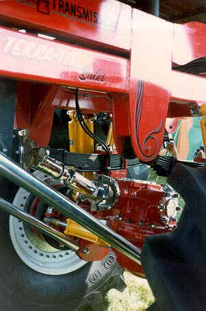
Here we have a beautifully executed example of both fish-plating and sub-framing techniques.
Eventually owners realized that those factory frames just were not up to the task of handling the type of loads being placed on them no matter how much steel you welded to them. So in keeping with Monster Truck philosophy that of course meant going to bigger frames! It occurred to someone that instead of pulling the drive train out from under a military truck and welding it under their pick-up truck frame, why not just mount that pick-up truck body on top of the military truck’s chassis. And thus the straight frame Monster Truck was born. This option solved some of the strength issues but created new challenges such as shortening the wheelbase, modifying cross members and fabricating body, engine and transmission mounts. This prompted some builders to start from scratch and fabricate a frame following their own specifications employing either C channel or box tubing. These frames typically were made from at least 1/4″ thick mild or high tensile steel ranging from 8″ to 12″ tall. Strong, but very heavy.
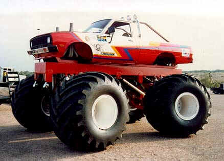
Most straight frames were constructed for strength but weight was not yet an concern.
It wasn’t long before Monster Trucks were racing side by side and weight as well as driver safety became an issue. While some experimented with aluminum as a frame material in an effort to cut weight, rollovers began to occur at higher speeds and the old bed mounted roll bars were no longer adequate. Therefore, in-cab roll cages became a requirement. To further strengthen these roll cages “kicker bars” were added to distribute the load onto more points and as a by product this also helped support the frame. Thus “triangulation” was introduced into the realm of Monster Trucks. This led to a major reversal in the trend and allowed for lighter frames with greater structural integrity. (A more detailed discussion of roll cage design will appear in a future installment of Monster Tech
Kicker bars were added to lighter straight frames providing them additional strength.
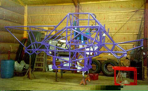
With the addition of more points of triangulation huge leaps in chassis rigidity were made. Straight main frames were shrunk down to as small as 3″ square or round tubing and also allowed for integral shock mounts. “Trusses” were added to the bottom side of the frame to provide further support and allow for better 4-link mount placement providing a solution to geometry problems inherent in early monster truck suspension designs.
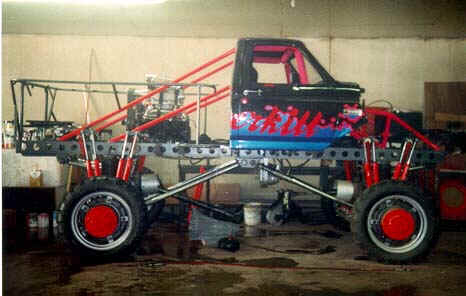
Triangulated chassis allowed for much smaller frame rails such as this example utilizing 3″ square tubing.
Soon after “tubular chassis” Monster Trucks began to appear on the scene. In most cases a bridge like structure made from 2″ diameter .120 wall tubing acts as a main frame with the roll cage structure tying it all together. This made for even lighter chassis to go along with the continually lighter drivetrains being employed.
An additional concern being addressed in the newer designs was “CG” (center of gravity). In an effort to provided for greater all around stability, drivetrain and accessory components were continually mounted lower in the chassis. This has reached a point where in some cases axle centerline can surpass engine crank centerline under full compression of the suspension! The general theory behind such a design is that the harder the landing to more the truck should have a tendency to right itself.
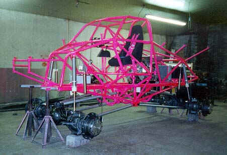
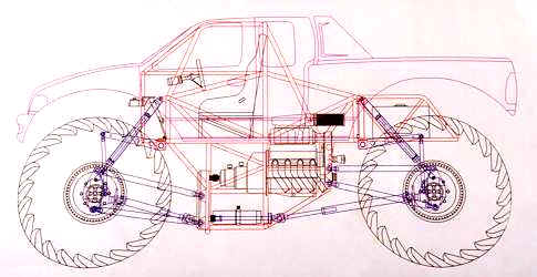
This is an example of a complex fully triangulated low CG tubular chassis.
But for the ultimate in light weight and low CG some future Monster Trucks may employ “spaceframe” chassis technology. This refers to a chassis where the entire structure acts as frame, mounts and cage in one singular unit. In some cases light weight enough to be carried around the shop by two non-super heroes.
How light weight can a spaceframe Monster Truck get? We may soon find out.
Innovations in chassis design have allowed Monster Trucks to reach car crushing weights in excess of 18,000 lbs. and dip down to below 8,000 lbs. in racing trim, all in the interest of greater performance and improved reliability.
|
Monster Truck Suspension Evolution – Part 1 |
|
by Marty Garza – Overkill Racing |
In the simplest of terms a Monster Trucks Suspension can be broken down to 3 major mechanisms: 1) Axle Location (i.e. Links), 2) Weight Support (i.e. Springs), and 3) Dampening (i.e. Shocks). As you will see there are often overlapping rolls performed by the components of each of these mechanisms, as well as secondary
functions not often considered.
As discussed in previous editions of Monster Tech, the basis of the original Monster Truck was the average family pickup truck. As such, early Monster Truck suspension was based on Detroit industry standard of the late 1970s, the ‘Leaf Spring’. Its design though simplistic performs 2 of the 3 major functions, that being axle location and weight support.
In most early Monster Truck designs suspension was primarily utilized to do little more than provided the desired ride height. To achieve the clearance required to sport the massive tires early designs employed a variety of methods ranging from tall ‘Lift Blocks’, large custom built multi-leaf ‘Spring Packs’ or highly ‘Arched Springs’.
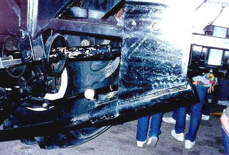
Deceiving, the immense size of these highly arched springs is not immediately apparent until you consider their scale in relation to the 5 ton military axles and 73″ tires depicted in this photo.
Still others opted to utilize the leaf springs off the very same military trucks where the axles were being salvaged. However relatively short flat springs such as these often necessitated the use of large ‘Dropped Spring Mounts’.
In order to clear massive 73″ tires, this builder incorporated the use of large dropped spring mounts and lift blocks.
These various methods of attaining height did little in the way of providing ‘Suspension Travel’ (vertical axle movement). Furthermore, each had drawbacks such as in the case of lift blocks which provided additional leverage against the springs causing wrap-up and failure (i.e. broken center pins or main leafs). To combat this builders added ‘Traction Bars’ to help support the springs. However lack of proper engineering often resulted in binding which would not allow for much if any travel. To fully understand this phenomena you must realize that axle path is not completely vertical throughout its travel. For an arched spring to proved vertical movement it must be allowed extend via a ‘Shackle’. Therefore due to its curvature, for the leaf spring to compress the horizontal distance between its solid mounted end and axle centerline must increase. This increase is called ‘Deflection’. The greater the arch in the spring, the greater the deflection illustrating a major drawback to the highly arched springs often utilized.

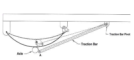
Note that the axle path in this illustration deflects rearward (A to B) through its travel due to the curvature of the leaf spring.
Likewise, downward angled solid traction bars travel in an arch deflecting opposite their pivot point. The steeper the angle, the more deflection. So when rearward mounted shackles were combined with centrally mounted traction bars, suspension travel was all but eliminated. Combating this required front mounted shackles and flatter (less steep) traction bars which traveled in an arch matching that of the spring. However this was not always possible and furthermore this setup produced deflection opposite the direction of impact which many considered less than ideal.
Although the leaf spring in this illustration deflects rearward (A to C), the solid traction bar deflects forward (A to B).
This combination precludes suspension travel.
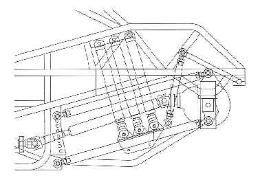
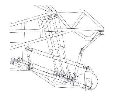
Eventually designs incorporated the use of ‘hydraulically dampened traction bars’. This basically consisted of a short hydraulic cylinder mounted on the end of a solid traction bar. Fluid is allowed to travel from one side of the cylinder to the other often via a ‘Flow Control Valve’. This allowed the leaf springs rearward deflection, and traction bars forward deflection, to be absorbed by the hydraulic cylinder allowing for more wheel travel.
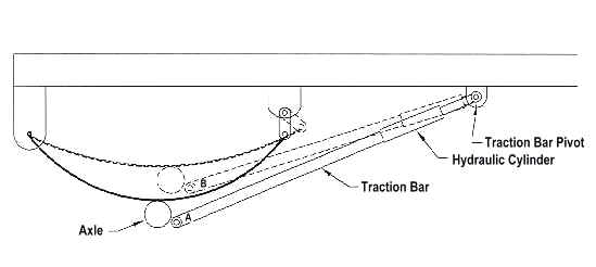
Hydraulically dampened traction bars compress rearward (A to B) absorbing the springs deflection allowing freedom of vertical movement.

Note the deflection indicated by the zip-ties on the shafts of these hydraulically dampened traction bars.
Never the less most builders utilized leaf spring packs with ‘Spring Rates’ (the amount of weight required to compress a spring 1″) intended for much greater ‘Sprung Weight’ (the weight supported by the springs). This excessive spring rate also inhibited suspension travel. Keep in mind that springs can only control the weight which they support. Components such as axles, wheels and tires (the bulk of the weight of a Monster Truck at that time) are not supported by the springs and are considered to be ‘Unsprung Weight’ and therefore can only be dampened by shocks. Therein lied another problem inherent in early designs.
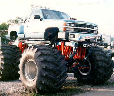
Filed under, What were they thinking? Notice the hydraulic traction bars mounted rigidly to the frame.
In this instance the traction bars are actually acting as springs and must bow to allow any suspension movement at all.
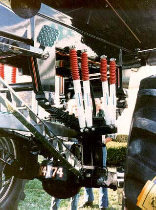
Due to the tremendous amount of unsprung weight builders often over dampened their suspensions with the use of numerous shocks. The problem is that shocks dampen in both compression (closing the shocks shaft) and rebound (extending the shocks shaft). That means that a certain amount of force is required to compress the shock. Add another and more force is required, and so on. Eventually with enough shocks you can reach a point where the load cannot easily overcome the resistance (dampening) they provide. What was left was a field full of oversprung, overdampened Monster Trucks with little to no suspension travel thus necessitating the use of stronger (heavier) components to withstand the abuse inflicted upon them.
Shocking! In this example nearly every available space was utilized to mount shocks. How many can you count?
As the saying goes, “Racing improves the breed”. So as Monster Trucks began racing side by side, greater consideration was placed on their suspension design. Lift blocks, highly arched springs, and heavy dropped spring mounts were replaced by long leaf springs with more correct spring rates. These long springs did not require as much arch to achieve the desired lift and therefor produced less deflection. Best of all, some examples achieved as much as 12″ of suspension travel providing more comfort for drivers and larger performance envelopes for these Monster Trucks. This was a much needed step in the right direction.
|
Monster Truck Suspension Evolution – Part 2 |
| by Marty Garza – Overkill Racing |
In this months edition of Monster Tech I continue my discussion of Monster Truck Suspension Evolution. As stated in Part 1., after initially struggling with poor suspension designs, builders began considering the shortcomings in their approach.
Although the ‘Hydraulically Dampened Traction Bars’ incorporated into ‘Leaf Spring’ suspensions provided for increased wheel travel, they also allowed for an undesirable side effect referred to as ‘Bump Steer’.
Remember in my discussion of ‘Deflection’ I noted that in a leaf spring suspension, axle path is not completely vertical. As such the axle typically deflects rearward several inches. This deflection was initially desirable in terms of impact absorption but as Monster Trucks began racing and speeds increased, this deflection also adversely effected handling and the ability for the driver to maintain a straight path down the track. This was due to the fact that the left and right side leaf springs work independently, so upon uneven landings the springs will deflect unequally. This differential is then amplified by the distance from spring centerline to wheel centerline. Therefore, if a truck takes a hard landing on the right front wheel and the right side spring deflects moving that side of the axle back but the left side spring sees little movement, the axle is no longer perpendicular to the chassis. In other words, “Right turn Clyde!”
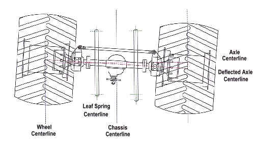
As you can see from this illustration if the right side leaf spring deflects 2″ more than the left side, due to the distance from centerline of the left spring to the wheel centerline of the right side, this actually pitches the axle nearly 7″.
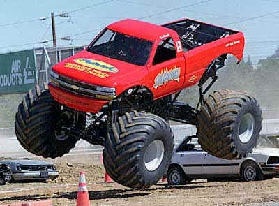
In those early racing days it was not uncommon to see trucks completely missing the second set of cars even at relatively slow speeds by comparison to contemporary racing Monster Trucks.
The solution to this dilemma came by separating the functions of weight support and axle location. The answer was ‘4-Link Suspension’.
In a ‘4-Link’ suspension axle location is achieved through the use of link bars which are typically mounted both above and below axle centerline which control fore and aft movement. In early designs lateral movement was controlled by an additional link mounted parallel to the axle referred to as a ‘Panhard Bar’. However, as suspension travel increased this relatively short link caused excessive lateral deflection offsetting the axles.
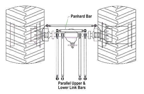
One end of the Panhard Bar mounts to the axle while the other end mounts to the chassis. This method keeps lateral movement in check when using parallel upper and lower link bars.
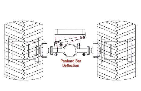
Panhard bars worked well but due to space limitations required rather short links.
This led to excessive lateral deflection as suspension travel increased.
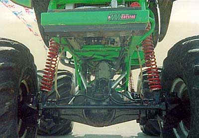
The solution came by angling the upper 4-link bars towards the center of the axle thereby placing one bar in compression and the other under tension while experiencing lateral loads.
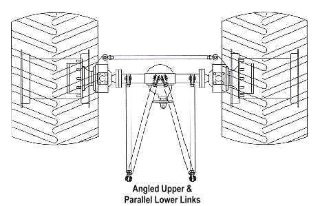
To this day the most effective method of providing lateral axle support involves the use of angled upper links.
Most early 4-link designs utilized unequal (shorter upper) link bars due to engine clearance problems and to allow for more lateral angle due to the narrower chassis in use at the time.
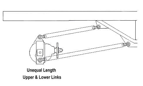
Shorter upper links provided more lateral angularity and kept them clear of important components such as engine oil pans.
This was not a problem until considerably longer travel suspensions were employed. This eventually became a problem due to the differences in deflection rates of the upper and lower links. This often made for undesirable pinion angle changes as well as ‘Caster’ changes which also adversely effect stability.
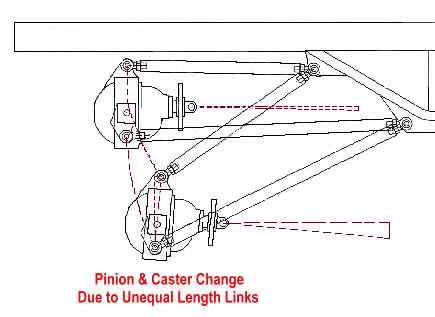
Note that as the suspension cycles the shorter upper links deflect more than the longer lowers. This in turn makes for changes in caster and pinion angle.
Eventually wider chassis designs incorporated equal length links which eliminated these problems.
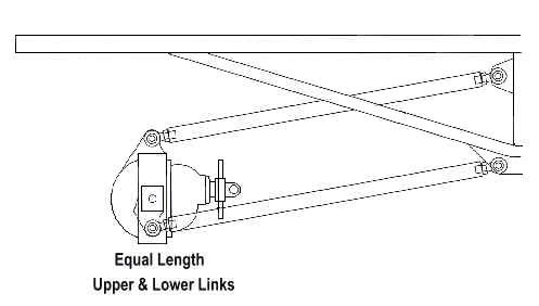
Equal length upper and lower links deflect equally and do not effect caster or pinion angle as long as they are vertically parallel to each other.
4-link bars typically employ the use of ‘Spherical Rod Ends’ which allow adjustability in axle centering and pinion angle while allowing freedom of movement without bind.
The most common Spherical Rod Ends used on today’s Monster Truck feature a 1.25″ male thread and 1″ through bolt.
The switch to 4-Link suspension allowed builders to achieve more desirable suspension parameters eliminating many of the limitations inherent in pure Leaf Spring suspensions. And, the longer links allowed for minimal deflection and bump steer. However remember, axle location is only part of the story. Some method was still needed to support the weight.
The easiest method of supporting the weight of these early 4-link Monster Trucks was to stick with the tried and true leaf spring. However, this time ‘Dual Shackles’ were employed allowing the spring to float (deflect in either or both directions) expunging them of axle location duties and relying on them strictly for weight support.
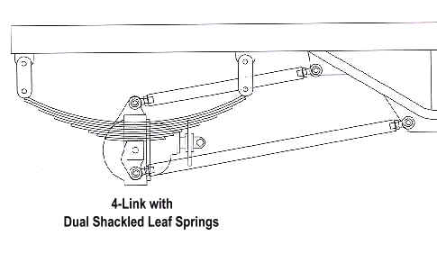
Dual Shackles allow the leaf spring to deflect in either or both directions without effecting axle location.
Another option was chosen by some based on ride height adjustability and major weight savings. This was the utilization of ‘Air Bags’. These consist of a rubber ‘Bellows’ (bag) attached to a ‘Piston’ (bell) which under compression is forced into the bellows effecting spring rate. An added benefit is that most incorporate an internal ‘Bump Stop’ which helped dampen bottoming of the suspension. These air bags worked adequately in some cases but were limited in spring rate availability and to a maximum of about 12″ of suspension travel.
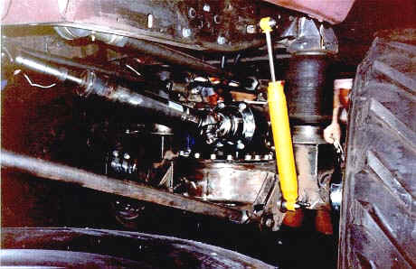
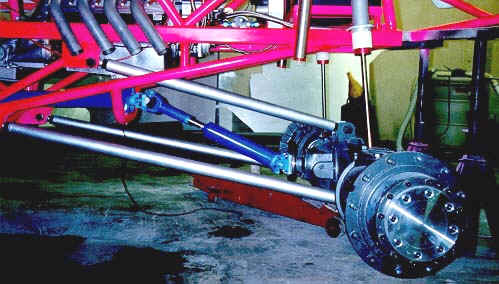
Here we see the use of Air Bags with unequal length upper and lower links and a panhard bar.
Eventually ‘Coil Springs’ became the method of choice due to the availability of custom winds. This allowed for the tailoring of spring rates to match the trucks sprung weight. These coil springs worked quite well but there was still one overriding limitation. The shock absorbers.
The longest conventional shocks available only provided 12″ of shaft travel and were not adequately adjustable. Then from far off in the desert of the West Coast came the solution and the new revolution in Monster Truck technology.
|
Monster Truck Suspension Evolution (Part 3.) |
|
by Marty Garza – Overkill Racing |
In the years following the advent of Monster Truck Racing, great strides were made in control and handling. However the single biggest revolution came from existing truck racing technology thriving in the west.
Since 1967 when Ed Pearlman decided that it might be fun to stage a race across the desert of Baja, California, guys like Parnelli Jones and Mickey Thompson struggled through many of the same teething pains Monster Truck racers were now facing. This gave them over 2 decades head start to figure out how to address the issues involved in controlling the suspension systems of trucks being launched into the stratosphere and making them survivable. The key was control of dampening. As such, vast resources were employed to develop race specific dampeners (shock absorbers) which could be tuned for individual applications.
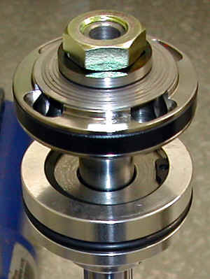
By the early 90s one of the major forces in this development was Kuster Company out of Long Beach, California. Chief engineer Lance King designed a large volume (3″ diameter) long stroke Coil-Over which as the name implies, is a shock with collars which allow a coil spring to be mounted over.
These race specific shocks could be custom Valved in the field. In other words the dampening characteristics for both Compression and Rebound can be tailored via a valve shim stack placed over orifices on a piston (valve body).
Shock Valving
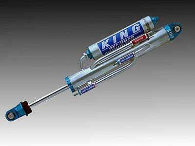
The King designed shock had external rebound adjustability via a clicker at the bottom of the shaft which could effect the dampening factor by as much as 25%. Control of rebound is especially important as it truly controls the attitude of the truck while airborne. The rate at which the shocks rebound (front shocks vs. rear shocks) in large part dictates whether the truck will carry a nose-high or nose-dive attitude.
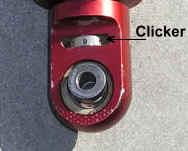
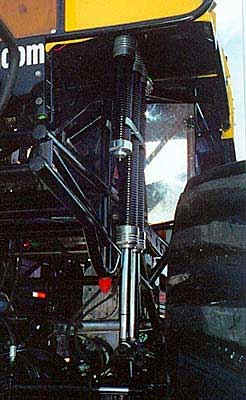
The clicker located at the bottom of the shaft on the King designed shock is used to control rebound.
This adjustment is useful in controlling a trucks flight attitude.
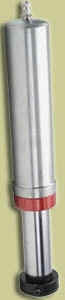
(This is not a King shock – but the same design. The clickers are no longer on the shocks)
In addition the coil-over design of the shocks allowed for spring pre-load and ride height adjustability. These shocks were used quite successfully by desert racers such as Walker Evens and were the logical next step in Monster Truck suspension evolution.
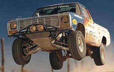
The success of Walker Evans is a testament to the outstanding performance of the King designed shock.
When approached with a proposal for developing a Monster Truck shock, King realized that based on existing Monster truck suspension designs which typically relied upon a 1:1 axle to spring movement ratio, a slightly lengthened version of his desert racing shock would be necessary. This led to the development of an 18″ stroke, 3″ diameter coil-over shock which relied on a 1″ shaft.
Dennis Anderson’s Grave Digger utilized coil-over shocks with very impressive results.
Having lived through this change over from conventional shocks to the King design coil-overs, I can definitively state that words cannot fully convey the quantum leap in performance and driver comfort offered by these shocks. Monster Truck racing has always been somewhat masochistic. The basic rule has always been, if the performance wasn’t painful, then you weren’t pushing the envelope. Though it may not be apparent to the spectators, the abuse inflicted upon the drivers takes its toll on their bodies. This can only truly be appreciated by someone who has “taken a ride on the wild side”.
I once took a radio personality “thrill seeker” for a ride during a freestyle performance. Personally I thought the guy was a few cards short of a full deck as he had just ridden as passenger on the back of a motorcycle while performing a dare-devil jump over a number of vans! So I took him out for a little ride. Nothing that I would consider extreme. But when my performance was over and the guy crawled out of the truck, he was as pale as a ghost and stated that he would do another motorcycle jump any day but he was NEVER getting back in a Monster Truck!!
That being said, the King designed shocks greatly expanded the Monster Truck performance envelope pushing the threshold way beyond that where such performance with conventional shocks would have resulted in injury to the driver. This also went hand in hand with greater truck reliability. This also appeased the show Promoters who prior to this were often faced with half the field of trucks being unable to perform the following day after a hard night of racing.
This leap however did not come cheap. These state-of-the-art shocks came with a premium price tag of about $1,200 each! At least only one was needed per corner. Add to this another $1000 for custom coil springs and the cost of going fast just got steeper.
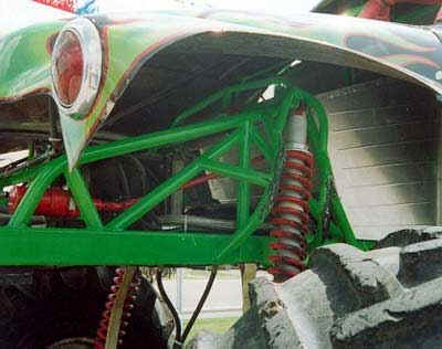
About this same time Bob Chandler was experimenting with an older desert racing shock design on his BIGFOOT 8 and 9 trucks which instead of a coil-over, relied upon nitrogen gas as a spring. This Gishi design had been largely discarded by desert racers due to heat induced gas pressure/ride height fluctuations. However whereas desert racers build up heat cycling their shocks millions of times throughout a race, Monster Trucks do not face these heat-induced issues.
Although eventually abandoned, initial nitrogen sprung designs by Chandler incorporated the use of a Cantilever system providing approximately 24″ of wheel travel. In this design the shocks were mounted up in the chassis and were hinged on a lever actuated by the axles via a solid link. Systems such as these allow for a tailored ratio of the axle to shock shaft movement. However such systems can be difficult to setup and tune unless they are designed to work with the specific spring curve characteristics of the shocks. Never the less a very long travel cantilever system is still being used quite successfully by Dan Patrick on the rear of his Samson Monster Truck.
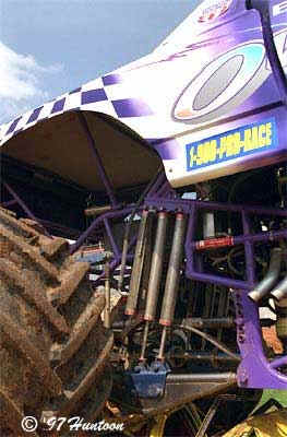
Dan Patrick incorporates a cantilever design in the rear of his Samson Monster Truck which as you can see provides a great deal of wheel travel.
The use of nitrogen sprung shocks as a method of suspending the trucks was used successfully but was not generally available to the masses until Chandler sold the rights to the design to trail Master Suspension for marketing.
Simultaneously, Steve Combs owner of the Knight Stalker Monster Truck developed a similar nitrogen gas shock in various lengths
(Currently up to 30″ stroke) which was also made available to the public. The KS Vitro Shock has gone on to become the most popular shock in Monster Truck history.
The Steve Combs built KS Nitro Shock has become the most commonly used shock on modern day racing Monster Trucks.
Nitrogen gas sprung shocks have the advantage of allowing for a great deal of ride height adjustment. I might point out that Nitrogen is simply utilized because it is more stable and less effected by temperature than air. In addition the use of nitrogen as a spring allow for some tuning of spring rate based on gas pressure. However, that which makes them great is also the Achilles Heel of their design.
Although they have become the cornerstone of Monster Truck suspension, surprisingly the vast majority of owners have no idea how they actually work. The single most common question concerning these shocks is, “what is holding the truck up?”. Although the most common response is “gas”, the true answer to that question is the displacement of oil.
Let me give you a simple analogy…
Picture a bath tub filled to the very brim with water. As you step in slowly, what happens? Water spills out onto the floor. And, as you step in further more water spill out, right? Now imagine that the bath tub is the body of the shock filled with oil, you are the shock shaft, and the floor is the shock reservoir.
When you stand out side of the tub you are the shaft fully extended (out of the oil). As you step in you displace water just as the shaft displaces oil. The water spills out onto the floor just as oil is displaced out of the shock body into the reservoir. Inside that reservoir is a piston with nitrogen gas on the opposite side of the oil. As oil is displaced out of the shock body into the reservoir, it moves the piston thereby compressing the nitrogen. So the oil acts as a lever transferring the movement of the shaft to the piston.
Therefore, the trucks weight is actually supported by the diameter of the shock shafts. How much oil they displace directly relates to the spring rate. Likewise, the volume of the reservoir dictates the Spring Curve (multiplication of spring rate). This is because as a gas is compressed its pressure rises exponentially. So with a given displacement (piston movement), the greater the volume of the air chamber, the more linear the spring rate. Conversely, the smaller the volume of the air chamber, the steeper the spring rate. This rise in pressure (spring rate) is often referred to as Ramping Up.
In my opinion (based on testing and data acquisition which we have performed) the problem with existing designs is that they utilize small displacement/small volume systems which rely on extremely high pressures. This makes for trucks which in order to achieve full suspension travel must be set very deep into the travel which does not make for much initial bump absorption. This is because the small volume chambers ramp up steeply and make for comparatively harsh ride characteristics as compared to coil springs. In addition, when extended, the spring rate drops off to essentially nothing so upon landing the trucks blow through the initial wheel travel as though it were not even there. But, when trying to address this and set at a taller ride height, these shocks typically ramp up so quickly that full travel cannot be achieved. This situation forces the tuner to opt for the lesser of the two evils.
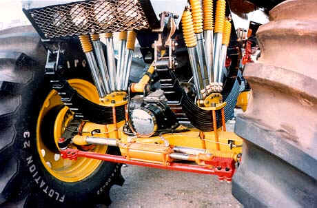
One method of getting around this problem developed by us in conjunction with King incorporated the use of Air Springs. These air springs more closely mimic a coil spring in operation and a shock in their appearance. These springs do not rely on oil displacement but instead on a solid 3″ diameter piston and large volume air chamber. This system allows for the use of very low air (nitrogen) pressure to attain desired ride height and exhibits a much more linear spring rate. Furthermore, the spring curve can be tailored by changing the volume of the air chamber and shape of the piston.
This air spring system was utilized on Extreme Overkill which incorporated the first Swing-Arm type suspension system to be used on a Monster Truck providing 36″ of wheel travel. In this application, the shocks and air springs were mounted on specially designed 4-link bars which provided a 2:1 overall shaft travel to axle travel ratio. Lever type systems like this work very well in conjunction with air springs because the suspension geometry can be designed with a falling Rate to offset the ramping up (rising rate) of the air spring.
Can you spot the Air Spring? Extreme Overkill was the first Monster Truck to incorporate a Swing-Arm type suspension system as well as air springs. Although nearly identical in appearance to the shock next to it, the shock furthest right is actually an air spring.
In a falling rate design the ratio of axle to shock shaft movement changes throughout their cycle for example from 1:1 (axle to shaft) at near full extension (rebound) to 3:1 at near full compression. In other words, whereas upon landing the axles may move 1″ for every 1″ of shock shaft movement, this ratio is variable to the point where as it nears bottoming may provide 3″ of axle movement for every 1″ of shock shaft movement.
In contrast, Rising Rate systems function conversely. As they compress the shocks see a higher ratio of movement in relation to the axles. However such systems work better with coil-overs as it enhances their progression.
Over 3 decades of trial and error have led Swing Arm suspensions to be the basis for 99% of elite level desert racing trucks. This is due in part to their reduction in shock shaft speeds proportionate to the shaft to axle movement ratio. This not only reduces heat build up but enhances seal reliability and makes for more supple dampening characteristics as the valving is not subjected to extremely high velocities of a 1:1 ratio system and is thereby more efficient.
These illustrations show how the swing arm suspension system incorporated into Extreme Overkill provided 36″ of wheel travel while utilizing 18″ stroke shocks.
One drawback inherent in all nitrogen sprung suspension systems is their lack of Body Roll control. Due to their spring curve and limited ability to control (comparatively) low speed dampening, Monster Trucks equipped with such systems have a tendency of leaning to one side or the other while maneuvering. To counteract this a method was employed which provides additional resistive force to any corner which is placed under a greater load than that opposite it. This system is referred to as a Sway Bar. Sway bars are essentially a torsion bar affixed to the chassis which is linked via lever arms to each side of the trucks axles. When moving together on an equal plane the sway bar does not come into play. But as more force is applied to one side than the other, such as in a turn, the bar is twisted acting as a spring assisting the nitrogen springs to resist this load. Because of the leverage applied by the long lever arms required on long travel Monster Trucks, their sway bars are typically 1 1/4″ to 1 3/4″ in diameter!
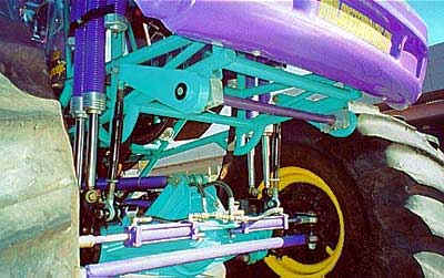
Nearly all modern day Monster Trucks utilize Sway Bars to control body roll. The long lever arms of the sway bar are attached to the axle via adjustable links. This provides the ability to level the trucks side-to-side should the sway bar get tweaked.
An additional benefit of sway bars is the reduction of deflection as referred to in Monster Truck Suspension Evolution Part 2. As sway bars inhibit axle articulation, this keeps the left and right side 4-link bars in a limited range in relation to each other minimizing deflection.
Another first incorporated into Extreme Overkill was the use of External Bypass shocks. Also designed by King, these shocks have multiple tubes with one-way valves welded to the out side of their shock can. These tubes can be staged and the valves can be adjusted externally to provide position sensitivity for the shock in both compression and rebound. This provides a great deal of in-the-field adjustment not previously available. Their advent has allowed teams to make drastic changes to shock valving even between rounds during a race.
The bypass tubes welded to the shock can provide staged independent adjustability for both compression and rebound.
Yet another technological innovation brought over from the desert incorporated into use on Extreme Overkill was the use of Air Bump Stops. These are small pneumatic cylinders mounted to the chassis which are pressurized and dampen the final 6″ of wheel travel as they come into contact with the axle and are compressed. This is a high tech version of the rubber snubbers found on virtually every pick-up truck currently in production.
These small Air Bump Stops are charged with nitrogen and provide additional dampening to the final 6″ of wheel travel before bottoming.
As you can see there is a lot to be said concerning Monster Truck Suspension systems. I believe that on the horizon you will see shock designs and suspension setups go in 2 different directions. I believe that as some builders will realize that it is not the amount of wheel travel available but instead the quality of usable wheel travel which is important. As such, some new designs will return to the use of shorter (18″ to 24″) travel setups with coil-over shocks utilizing Dual Rate springs. These dual rate setups incorporate the use of stacked coil springs with two different rates. These allow for lower ride heights and greater progression in the spring curve.
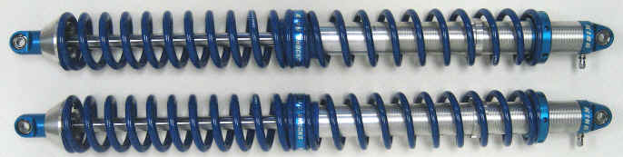
Coil-overs with Dual Rate springs provide for more range of ride height adjustment and progression than standard coils. Note the divider between the coil springs.
Yet other longer travel designs (28″ to 42″) may benefit from the next generation large displacement/large volume nitrogen sprung shocks. A patent is currently being pursued for a unique design which I believe may offer the best of both worlds in the form of the most tunable system yet offered. This system may even have the ability to be upgraded to semi-active as well as fully active computer-controlled dampening should enough interest in such a system exist.
This has been a lengthy article which yet did not touched upon several variations and issues. But, from all of this I believe that it is clear that as suspension designs improve and evolve, Monster Truck drivers will continue to push the envelope of their performance in a never-ending quest for speed.
About The Author
Jim Oaks is the founder of TheRangerStation.com, the longest-running Ford Ranger resource online since 1999. With over 25 years of hands-on experience building and modifying Ford Rangers — including magazine-featured builds like Project Transformer — Jim has become one of the most trusted authorities in the Ford Ranger off-road and enthusiast space.
Since launching TheRangerStation.com, Jim has documented thousands of real-world Ranger builds, technical repairs, drivetrain swaps, suspension modifications, and off-road adventures contributed by owners worldwide. TheRangerStation.com has been referenced in print, video and online by enthusiasts, mechanics, and off-road builders looking for practical, and experience-based information.