
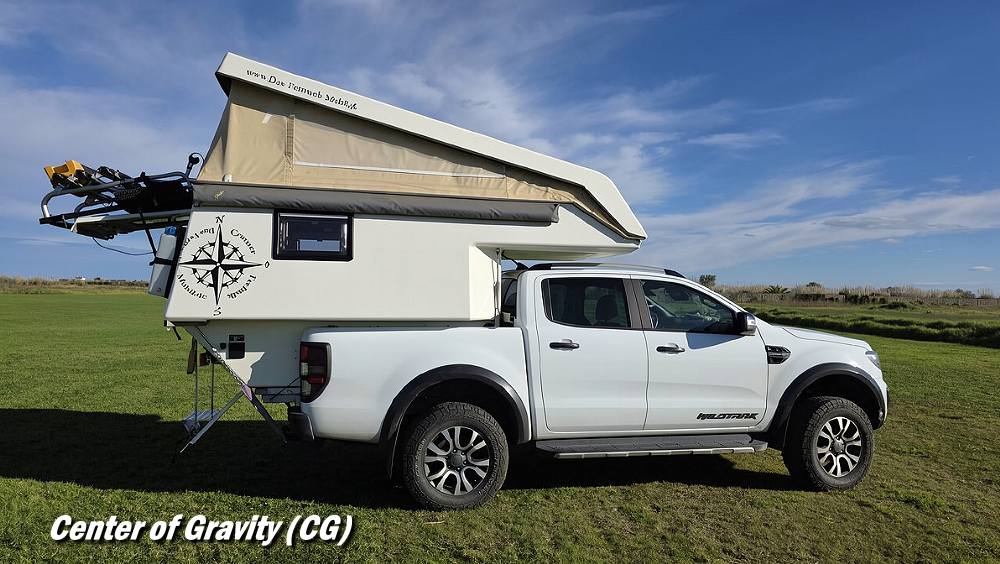
Introduction
Whether you’re building a 4-link suspension, an off-road vehicle, or you enjoy overlanding, you’ve likely heard the term ‘Center of Gravity’. If you drive a vehicle off-road or you haul things in your truck, it’s a term you should know and understand. I used a Ford Bronco and Bronco II for the drawings in this article, but the information here can be applied to Ford Rangers, Explorers or any other vehicles.
What is Center of Gravity
The Center of Gravity (CG) is the single point where a vehicle’s weight is effectively concentrated and balanced. The location of the center of gravity is influenced by the distribution of all components, including the engine, frame, suspension, passengers, cargo, fuel, and accessories. A lower center of gravity generally improves stability, while a higher center of gravity increases body roll, weight transfer, and rollover risk—especially on uneven terrain or during sharp turns.
Center of gravity exists in three dimensions. Longitudinal center of gravity describes the front-to-rear balance of the vehicle, lateral center of gravity describes side-to-side balance, and center of gravity height measures the vertical distance from the ground to the point where the vehicle’s weight is balanced. While all three affect handling and stability, center of gravity height is often the most critical factor in off-road stability, suspension behavior, and rollover tendency.
Static vs Dynamic Stability
A vehicle’s center of gravity does not change location every time the vehicle moves, but the forces acting on that mass do change. During acceleration, braking, cornering, climbing, or off-camber driving, momentum and weight transfer can dramatically affect how stable a vehicle feels and behaves.
Lower tire pressure used during off-road driving improves traction and ride quality, but it also changes how the tire sidewalls support the vehicle. Softer sidewalls allow more tire deformation during off-camber driving, which can reduce lateral stability and make the vehicle feel less controlled near its rollover limits.
Real-World Stability vs. Calculated Stability
Calculated rollover angles are theoretical static thresholds. They assume a rigid vehicle sitting motionless on a perfectly uniform surface. In the real world, vehicles often roll over at angles lower than their calculated static limits due to suspension movement, shifting cargo, momentum, terrain irregularities, and changing traction conditions.
Suspension Movement (Body Roll): When a vehicle leans on a side slope, the downhill suspension compresses while the uphill suspension extends. This body movement shifts the vehicle’s weight downhill and reduces the available stability margin compared to a rigid static calculation.
Cargo Shifting: Water containers, refrigerators, tools, recovery gear, and unsecured cargo can shift toward the downhill side of the vehicle when tilted. This movement changes weight distribution and can move the center of gravity closer to the rollover point.
Momentum and Kinetic Energy: Static rollover calculations assume the vehicle is not moving. In real off-road conditions, momentum creates additional forces that can rapidly destabilize a vehicle when hitting rocks, ledges, ruts, or uneven terrain.
Wheel Hop and Bouncing: Applying too much throttle while climbing obstacles can cause wheel hop or suspension bouncing. As the vehicle unloads and regains traction, sudden weight transfer and impact forces can reduce stability and increase rollover risk.
Abrupt Traction Changes: Vehicles sometimes slide sideways on loose dirt, mud, snow, or gravel without rolling because the tires continue slipping. However, if the sliding tires suddenly regain traction against a rock, rut, or firm surface, the vehicle may pivot around the tires and roll unexpectedly.
Steering Inputs: Sudden steering corrections on off-camber terrain can rapidly shift weight across the chassis. Aggressive steering inputs may further destabilize a vehicle that is already near its rollover threshold.
Ultimately, theoretical rollover angles only describe a vehicle under controlled static conditions. In real-world off-road driving, tire deformation, suspension movement, cargo shifting, terrain impacts, and momentum can significantly reduce the vehicle’s actual rollover threshold.
Why Vehicles Roll Over
Before we get any further, understand that vehicles rarely roll over simply because they are “top heavy.” Rollovers usually occur when momentum, weight transfer, traction, suspension movement, and a pivot point combine to rotate the vehicle beyond its point of recovery. A vehicle with a relatively high center of gravity can remain stable if traction and weight transfer stay controlled, while a lower vehicle can still roll if momentum and terrain forces overwhelm the tire support area.
In most real-world rollovers, one side of the vehicle becomes the pivot point the vehicle rotates around. This may be caused by a tire digging into soft terrain, striking a rock or obstacle, sudden traction gain, or suspension compression. Once the vehicle begins rotating around that point, momentum and gravity can continue the rollover even if the original triggering force disappears.
Terrain irregularities often initiate this rotation. Rocks, ruts, ledges, washouts, or sudden traction changes can abruptly stop or redirect one side of the vehicle while the remaining mass continues moving. Even vehicles with relatively low centers of gravity can roll if momentum and traction forces suddenly rotate the chassis outside the tire support base.
One of the challenges of off-road driving is that a vehicle can feel stable right up until the moment stability is lost. Suspension movement, tire deformation, shifting cargo, and uneven terrain can gradually reduce the available stability margin without obvious warning to the driver. This is why theoretical rollover angles should never be viewed as safe operating limits in real-world terrain.
Why Center of Gravity Matters In Suspension Design
Center of gravity height is an important measurement when designing or tuning a suspension system, especially with linked suspensions such as a 4-link. In suspension geometry, center of gravity height acts as a reference point used to calculate how the vehicle’s weight transfers during acceleration, braking, climbing, and descending.
As the vehicle accelerates or brakes, momentum causes weight to shift between the front and rear axles. Suspension designers use center of gravity height along with wheelbase, suspension link angles, and tire traction to predict how the chassis will react under load. These calculations influence anti-squat, anti-dive, traction, suspension unloading, and overall vehicle stability.
This is one reason why center of gravity is important beyond simple rollover concerns. It affects how a vehicle behaves anytime weight transfers through the chassis and suspension.
Center of Gravity in Off-Road and Overlanding Vehicles
The importance of the center of gravity in off-road and overlanding vehicles lies in how it dictates the vehicle’s stability during dynamic maneuvers and on uneven terrain. While dedicated off-roaders maintain a consistent center of gravity due to minimal cargo, overlanding vehicles often face fluctuating and dangerously high center of gravity levels due to heavy trip gear.
How Weight Placement Changes Stability
Weight placement directly affects the “roll angle,” which is the point at which a vehicle’s weight vector falls outside its wheel track, causing a rollover. In overlanding, every pound added shifts this balance point. Improperly placed weight can make steering unpredictable, increase braking distances, and reduce traction on the very wheels that need it most.
High Weight and Roof Loads
Heavy roof loads should be packed with extreme care. Lightweight bulky items such as sleeping bags, folding chairs, and empty storage containers are generally safer roof cargo than tools, fuel cans, spare parts, or water containers. The heavier the roof load becomes, the more unstable the vehicle will feel during off-camber driving, emergency steering corrections, and uneven terrain transitions.
Body Roll: Elevated weight acts as a lever, increasing body roll and swaying during turns or on side slopes.
Rollover Risk: A loaded roof rack can drop a vehicle’s Static Stability Factor significantly; for example, adding ~230 lbs. to a Bronco / Bronco II’s roof can increase its rollover risk by more than half.
Emergency Handling: High loads delay steering response and make sudden maneuvers, like swerving for a hazard, much more likely to result in a tip-over.
Rear and Cantilevered Weight
Spare tire carriers, refrigerators, fuel cans, and storage boxes mounted behind the rear axle can significantly affect how a vehicle behaves on steep climbs, descents, washboard roads, and rough terrain. Even relatively small amounts of weight positioned far behind the rear axle create leverage that affects handling, suspension behavior, steering, and chassis stress.
The Pendulum Effect (Handling): Heavy rear weight can make the rear of the vehicle feel unstable on rough terrain. On washboard roads, bumps, or sudden steering corrections, the added weight behind the axle can increase fishtailing, rear suspension bouncing, and side-to-side instability.
The Fulcrum Effect (Steering): Weight hanging far behind the rear axle acts like a lever against the chassis. This can reduce front tire contact pressure, making the steering feel lighter and less responsive, especially during steep climbs or when accelerating uphill.
Braking and Descents: Heavy rear loads can reduce braking stability on uneven descents. If the rear tires lose traction or bounce on rough downhill terrain, the added rear leverage can make the vehicle more difficult to control.
Chassis Stress: Rear-mounted cargo carriers, oversized spare tires, and heavy bumper systems place additional stress on the frame and suspension mounts. Repeated impacts and vibration on rough trails can eventually contribute to metal fatigue, loose mounts, or frame cracking on some vehicles.
Because of these effects, heavy recovery gear, spare parts, fuel, and water should be carried as low and as close to the area between the axles as practical.
Track Width vs. Height
The relationship between track width (distance between wheels on the same axle) and center of gravity height is the fundamental trade-off of off-road design.
Stability Ratio: Widening the track (via offset wheels or spacers) can offset some of the stability loss from a lift kit or roof load.
The Trade-off: While a higher vehicle provides better ground clearance for obstacles, it inherently raises the center of gravity. To remain stable, a taller vehicle should ideally be wider.
A suspension lift does not automatically make a vehicle unstable, but increasing ride height raises the center of gravity farther above the tire contact patches. This increases the leverage acting on the chassis during cornering, off-camber driving, and sudden weight transfer events. Even with stiffer springs or sway bars, the higher center of gravity still reduces rollover resistance.
Center of Gravity Calculation Variables
The following variables and abbreviations are used in the center of gravity calculations throughout this article. These measurements are used to determine a vehicle’s center of gravity height, weight transfer characteristics, and overall stability. While the math may appear complicated at first, each variable simply represents a physical measurement or weight value taken from the vehicle during the testing process.
| Variable | Description | Units |
|---|---|---|
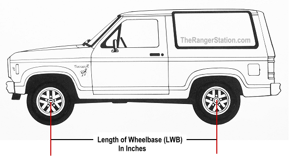
| LWB | Length of the wheelbase measured from axle centerline to axle centerline. | Inches |
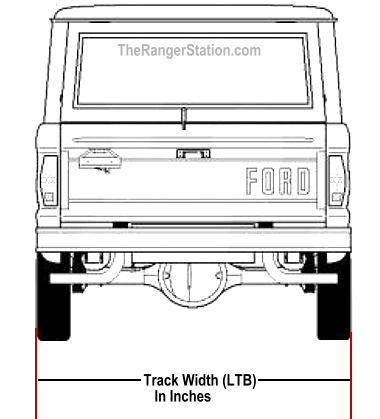
| LTB | Track width measured from the outer edge of one tire to the outer edge of the opposite tire. | Inches |
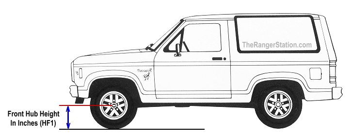
| HF1 | Height from the ground to the center of the front axle hub with the vehicle sitting level. | Inches |
| HF2 | Height from the ground to the center of the front axle hub after the front has been elevated. | Inches |
| HFD | Difference between front hub height when elevated and front hub height when level. (HFD = HF2 − HF1) |
Inches |
| WF | Weight on the front axle with the vehicle level. | Pounds |
| WR1 | Weight on the rear axle with the vehicle level. | Pounds |
| WR2 | Weight on the rear axle after the front of the vehicle has been elevated. | Pounds |
| WRD | Additional weight transferred to the rear axle when the front axle is elevated. (WRD = WR2 − WR1) |
Pounds |
| WT | Total vehicle weight. | Pounds |
| LWBN | The shortened horizontal wheelbase created when the front of the vehicle is elevated. (LWBN = SQRT (LWB² − HFD²)) |
Inches |
| WBCG | Wheelbase Center of Gravity location measured behind the front axle. (WBCG = (1 − (WF / WT)) × LWB) |
Inches |
| WTCG | Track Width Center of Gravity location measured from the passenger side outer tire edge. (WTCG = (1 − (WP / WT)) × LTB) |
Inches |
| WP | Weight carried on the passenger side tires. | Pounds |
| HTCG | Height of the vehicle’s Center of Gravity above the tire contact patches. (HTCG = HF1 + ((WRD × LWB × LWBN) / (WT × HFD))) |
Inches |
Preparing Your Vehicle
Before you can measure and weigh your vehicle, you need to have it setup and loaded exactly how you would if you were taking it off-road or overlanding. This includes your passenger if one normally accompanies you. This is vital to accurately determine the off-road center of gravity and rollover angles of your vehicle.
Off-Road Vehicle: For me, my off-road vehicle always has the same configuration. My recovery gear, tool bag and even my cooler is in the same location every time I take it off-road.
Overlanding: I understand that this can be harder for overlanders. Some of you feel like you need to take everything including the kitchen sink with you when you pack. Because of this, your center of gravity will always be changing. You’ll need to load the vehicle the way you would do it for every trip. Even the cooler / fridge. It would be a good practice to limit yourself to what you know you’ll need and stop overpacking with everything you think you might need or want.
Measuring Your Vehicle / Measured Values
You will need the following tools to measure and weigh your vehicle:
- Tape Measure
- Access to a truck weighing scale for approximately 5-minutes
- A means to elevate the front tires of your vehicle at least 24-inches off the ground (ramps, jacks, blocks, etc.)
- A Helper
Make all measurements accurate to a 1/16 of an inch.
Below are the weights and measurements we will be working with in this example. These are fictitious weights and dimensions for a fictitious vehicle for the purpose of this example.
For the purposes of these stability calculations the track width is the outside tire edge to the outside tire edge.
| Label | Value | Description of Measured Values |
| Lengths | ||
| LWB | 95 in. | Length of the Wheelbase (Axle center to axle center) |
| LTB | 65 in. | Width of the Track. (Outer tire edge to outer tire edge) |
| Heights | ||
| HF1 | 17.4 in. | Height of Front Axle Hub (center) from the level ground. |
| HF2 | 42.7 in. | Height of Front Axle Hub (center) from ground while Front is Elevated. |
| Weights | ||
| WF | 2,600 | Weight on Front Axle with Vehicle Level |
| WP | 2,100 | Weight on Passenger side |
| WR1 | 2,200 | Weight on Rear Axle with Vehicle Level |
| WR2 | 2,415 | Weight on Rear Axle when Front is Elevated |
Convert any fractions to decimal values. For example, a wheelbase measurement of 92-5/16 inches would be converted to 92.3125 inches. LWB = 92.3125
Here is a table to assist you in converting fractions to decimal format.
Fractions to Decimal Conversion Chart
| Fractions of an Inch | Decimal |
| 1/16 | 0.0625 |
| 1/8 | 0.1250 |
| 3/16 | 0.1875 |
| 1/4 | 0.2500 |
| 5/16 | 0.3125 |
| 3/8 | 0.3750 |
| 7/16 | 0.4375 |
| 1/2 | 0.5000 |
| 9/16 | 0.5625 |
| 5/8 | 0.6250 |
| 11/16 | 0.6875 |
| 3/4 | 0.7500 |
| 13/16 | 0.8125 |
| 7/8 | 0.8750 |
| 15/16 | 0.9375 |
Calculated Values
Using the data values you recorded above, the following values will be calculated and used in your efforts to determine the center of gravity and rollover angles.
| Label | Value | Description of Calculated Values |
| Calculated Values | ||
| HFD | 25.3 in | Difference between Front Hub Elevated and Front Hub when Level. (HFD = HF2-HF1) |
| LWBN | 91.57 in | Length of wheelbase when front is elevated. (LWBN=SQRT (LWB^2-HFD^2) |
| WRD | 215 lbs | Weight added to rear axle when front axle was elevated. (WRD = WR2 – WR1) |
| WT | 4,800 | Total Weight of your vehicle.
(WT = WF + WR1) |
Length of Wheelbase – LWB
Measure your vehicle’s wheelbase length while it is sitting on level ground and fully prepared for an off-road or overlanding trip. Do not use the known stock wheelbase for your vehicle. If you’ve added a lift, it could have affected the length of the wheelbase. It’s always best to use actual measured values.
Your vehicle’s wheelbase is the distance between the centers of the front tire footprint on the ground and the rear tire footprint on the ground. This is a bit difficult to measure accurately; however, we can get it by measuring the distance between the axle hubs.
With a friend, measure the distance between the center of the front axle hub and the center of the rear axle hub. This will be equal to the length of your vehicle’s wheelbase.
Below is a drawing of what you will need to measure to capture the wheelbase length.
Width of Wheel Track Base – LTB
Measure the distance between the outer edges of your rear tires. This is the track width of your vehicle. Convert any fractions to decimal values and record this measurement in inches as LTB. For the purposes of rollover and stability calculations, this method measures track width from the outer edge of one rear tire to the outer edge of the opposite rear tire.
While factory track width specifications are often measured from tire centerline to tire centerline, using the outer tire edges better represents the vehicle’s overall support base and stance width.
Below is a drawing of the measurement you need to take.
Front Axle Height – HF1
Measure the distance from the center of your front hub to the ground and record this as HF1.
Be sure your vehicle is sitting on level ground when you do this.
Weighing Your Vehicle
With your vehicle prepped (see above), you’ll need to take it somewhere to weigh it. Don’t forget to bring what you’ll be using to raise the front end.
Potential Scale Locations
- Truck Stops
- Agricultural Centers (Bulk Grain Sales)
- Salvage Yards
- Recycling Centers
The scale you choose should be accurate to at least 5 lbs. (1 lb. would be better.)
You’ll need about 10-minutes on the scale, so I would refrain from visiting a busy scale. Businesses that weigh scrap or grain may be more accommodating.
Most scales have guardrails or posts along the sides of the scale. If you find a scale with room to just park the passenger side tires on the scale, you’ll also be able to measure lateral center of gravity. Lateral center of gravity describes the vehicle’s side-to-side balance and can help identify uneven weight distribution across the chassis. This can be useful when evaluating suspension lean, cargo placement, or side-to-side weight bias caused by components such as fuel tanks, batteries, tool storage, or permanently mounted equipment.
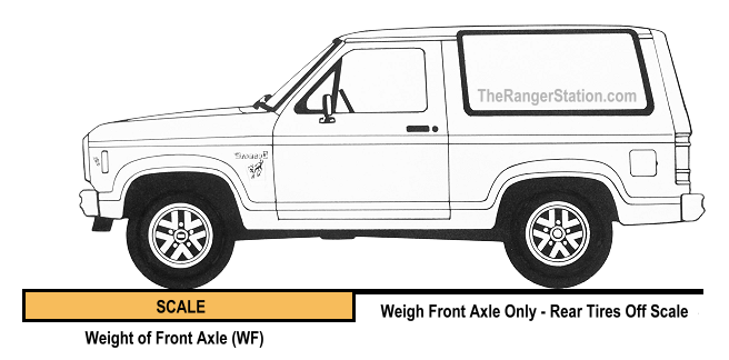
Front Axle Weight – WF
Weigh the front axle of your vehicle and record this weight as WF. To do this, pull only your front tires onto the scale.
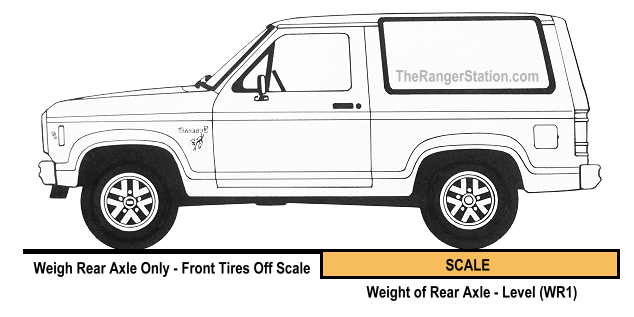
Rear Axle Weight – WR1
Pull forward so that the front tires are off of the scale and only weigh the rear axle.
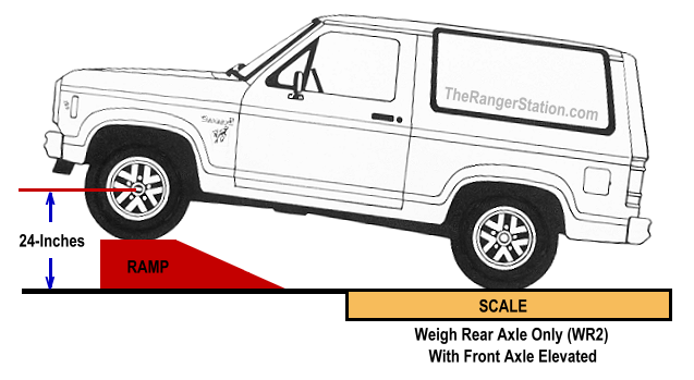
Rear Axle Weight With Front Elevated – WR2
You must lift the front axle of your vehicle up by the tires so that the hub is at least 24-inches from the ground. Whatever is lifting the front axle off of the ground CANNOT be on the scale.
DO NOT USE A JACK to do this. The vehicle must rest on its tires at normal suspension loading or the geometry and weight transfer calculations will be inaccurate. Record this weight as WR2.
Record the distance from the ground to the center of the elevated front hub as HF2.
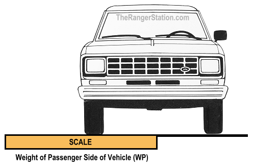
Passenger Side Weight – WP
Weigh the passenger side of your vehicle by pulling only the passenger side tires on the scale plate. Record this weight as WP.
You have now finished collecting all the data you will need to determine your vehicle’s center of gravity and rollover angles. All that is left to do is calculate a few formulas.
Calculating the Centers of Gravity
The Center of Gravity Height (HTCG)
The height of your vehicle’s Center of Gravity (HTCG) is not quite as easy to determine.
Calculating the HTCG is a bit more difficult to accomplish. It’s difficult for some people to even visualize, and difficult for me to explain.
Let me give it a shot.
When you went about measuring and weighing your vehicle, one of the things you did was lift the front axle (at least 24 inches higher than it would be on level ground) and then you weighed the rear axle.
When you lifted the front, you in effect shortened the wheelbase as it relates to gravity. In other words, the horizontal distance between the front and rear tire contact patches became shorter than what it is on level ground.
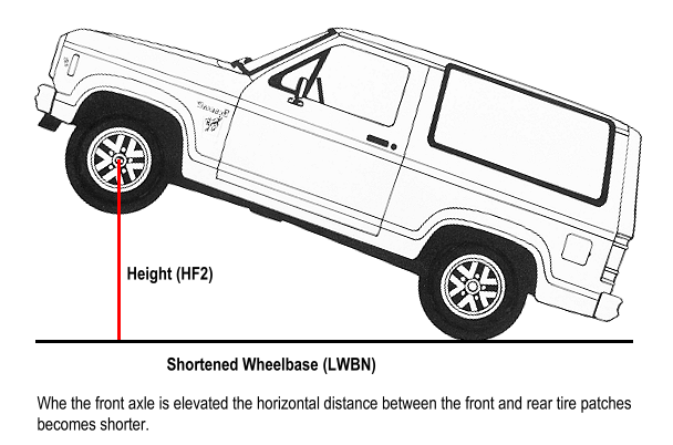
Now, if we can measure how high we lifted the front axle, calculate the length of this shortened wheelbase, and determine how much weight was added to the rear axle when we lifted the front, we will be able to calculate your vehicle’s center of gravity Height (HTCG).
Here are three formulas you must solve before you can get to the HTCG.
HFD = HF2 – HF1 = Height difference between front axle level and elevated
HFD = 42.7 – 17.4
HFD = 25.3 inches
LWBN=SQRT (LWB^2 – HFD^2) = Length of the shortened wheelbase when elevated
LWBN=SQRT (95^2 – 25.3^2)
LWBN=SQRT ((95 x 95) – (25.3 x 25.3))
LWBN=SQRT (9025 – 640.09)
LWBN=SQRT (8384.91)
LWBN=91.57 inches
WRD = WR2 – WR1 = Weight added to rear axle
WRD = 2,415 – 2,200
WRD = 215 lbs.
OK, now you have all the data needed to find the Height of your vehicle’s center of gravity (HTCG).
Here’s the formula.
HTCG = HF1 + ((WRD x LWB x LWBN) / (WT x HFD)) = Your vehicle’s CG Height
HTCG = 17.4 + ((215 x 95 x 91.57) / (4,800 x 25.3))
HTCG = 17.4 + (1,870,317.2 / 121,440)
HTCG = 17.4 + 15.40
HTCG = 32.80 Inches above the tire contact patches
The Wheelbase Center of Gravity (WBCG)
The easiest center of gravity coordinate to find is where the center of gravity lies relative to your vehicle’s wheelbase.
The weight on your vehicle’s front and rear axles is directly proportional to the location of the center of gravity along your vehicle’s wheelbase. In fact, it is a direct inverse ratio. If 100% of the weight of your vehicle was located on the front axle, the center of gravity would be located ZERO inches, or 0% of the wheelbase distance from the front axle. If the weight were distributed 60% on the front axle, then the center of gravity would be located 40% of the wheelbase distance from the front axle.
To calculate your vehicle’s WBCG (Wheelbase Center of Gravity) you will use the data values you measured and recorded earlier.
Let’s use the fictitious data from our fictitious vehicle recorded above.
LWB = 95 inches = Wheelbase in Inches
WF = 2,600 lbs = Weight on Front Axle
WT = 4,800 lbs = Total weight of vehicle
The following formula will enable you to determine in inches where the WBCG is located behind your vehicle’s front axle.
(1 – (WF / WT)) x LWB = WBCG location, in inches, behind the front axle.
(1 – (2,600 / 4,800)) x 95 =
(1 – 0.541667) x 95 =
0.46 x 95 = 43.54 Inches behind the front axle
The Wheel Track Center of Gravity (WTCG)
If you were able to weigh just the passenger side of your vehicle, then you can calculate the WTCG (Wheel Track Center of Gravity).
The location of your vehicle’s WTCG is calculated in much the same way as you just calculated the WBCG.
The WTCG coordinate location is a direct inverse ratio of the weight on each side of your vehicle to the wheel track.
Here are the data elements you will need to use for this formula.
LTB = 65 inches – Width of your wheel track
WP = 2,100 lbs – Weight on passenger side of your vehicle
WT = 4,800 lbs – Total weight of your vehicle
The following formula will enable you to determine in inches where the WTCG is located from the outer tire edge on the passenger side of your vehicle.
Substitute the data values you measured and recorded and then simplify and solve the formula as in this example.
(1 – (WP / WT)) x LTB = WTCG in inches, from the passenger side tire edge
(1 – (2,100 / 4,800)) x 65 =
(1 – 0.4375) x 65 =
0.5625 x 65 = 36.56 Inches from the passenger side outer tire edge
Rollover Angles
We now know the three dimensions (points) that define the 3D center of gravity of your vehicle.
In the examples above we know that the center of gravity points of our fictitious vehicle are:
- 43.54 Inches behind the front axle
- 36.56 Inches from the passenger side outer tire edge, and
- 32.80 Inches above the vehicles tire contact patches.
These three coordinates define the 3-dimensional location of your vehicle’s center of gravity.
Understanding the Vehicle’s Stability Zone
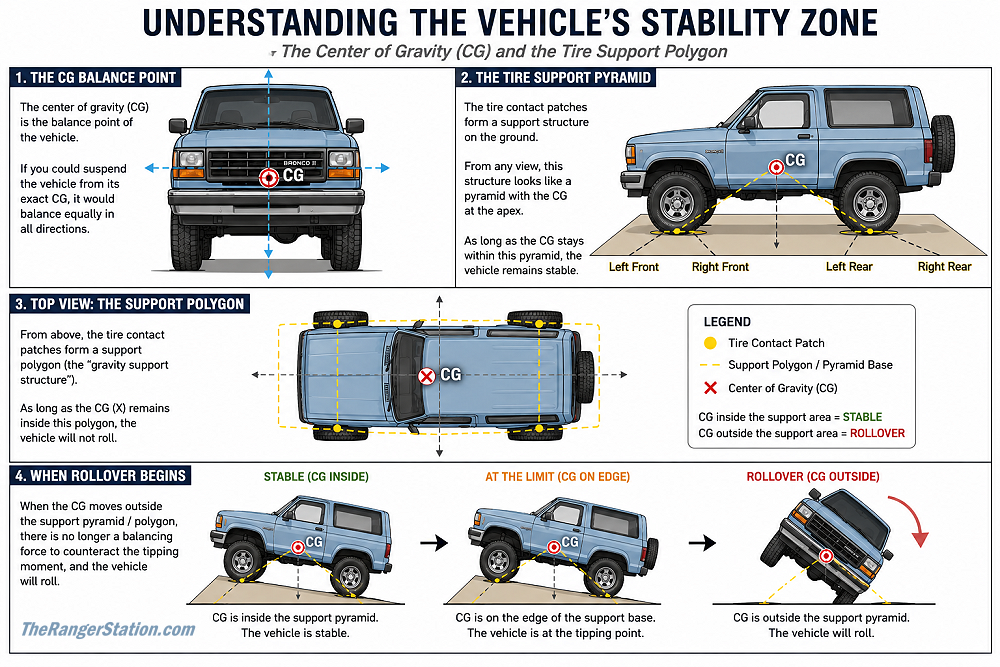
Your tires create the vehicle’s support base on the ground. As long as the vehicle’s center of gravity remains within that support area, the vehicle will remain stable.
You can visualize this as a pyramid extending upward from the tire contact patches to the vehicle’s center of gravity. A wider track width creates a larger stability base, while a lower center of gravity lowers the top of the pyramid and improves stability.
Although the center of gravity may not be perfectly centered within the vehicle, stability is maintained as long as it remains inside the tire support base.
As the vehicle leans, climbs, descends, or corners, the center of gravity remains fixed relative to the vehicle itself, but its vertical projection shifts relative to the tire contact patches. If the center of gravity moves outside the vehicle’s stability zone, the vehicle will begin to roll.
The center of gravity does not physically slide around inside the vehicle during normal operation. What changes is the direction of gravity relative to the vehicle and the tire contact patches supporting it.
Anatomy of a Rollover
If you position your vehicle in such a way that the center of gravity is moved outside the gravity support structure of your tires, your vehicle will become unstable and will roll.
In some situations a vehicle may slide before it rolls, especially on loose dirt, mud, snow, or gravel where the tires lose traction early. On high-traction surfaces such as dry rock or pavement, the tires may continue gripping while the center of gravity moves outside the stability zone, making a rollover more likely.
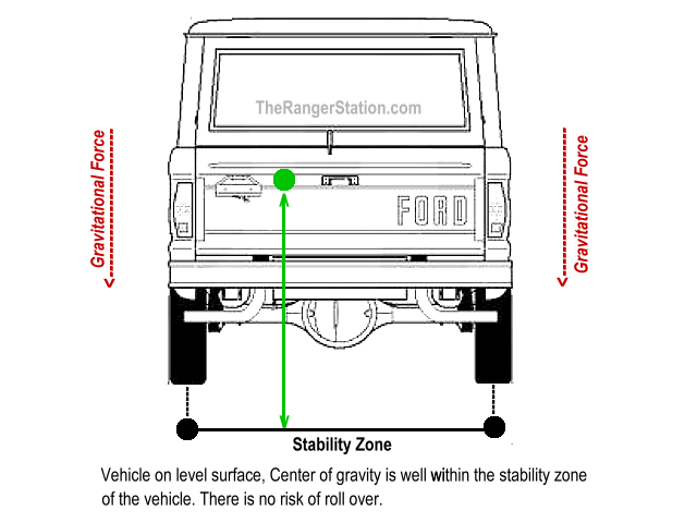
Let’s look at this from another view, from the rear.
When your vehicle is on level ground looking from the back the center of gravity (Green line) is contained between the driver and passenger side tires, or in other words, within the stability zone (support structure).
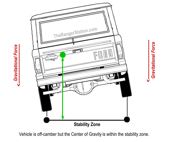
As your vehicle is positioned somewhat off-camber to the driver’s side, the center of gravity (Green line) will move closer to the edge of the stability zone.
Note that the center of gravity did NOT MOVE in relation to the vehicle itself.
If you position your vehicle too far off camber, the center of gravity (Green Line) will move outside the stability zone created by your tires and your vehicle will roll over.
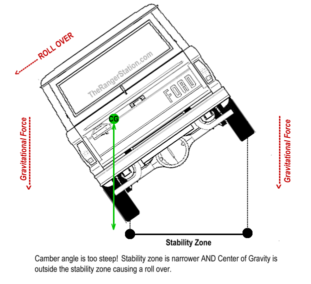
Why Did It Roll Over?
You roll because the center of gravity is no longer supported within the vehicle’s stability zone formed by the tires.
This is a basic law of physics.
If the center of gravity moves outside the tire support base, the vehicle will continue rolling until another surface stops the motion.
Rearward Roll Over
Here is what this looks like for a rearward roll over.
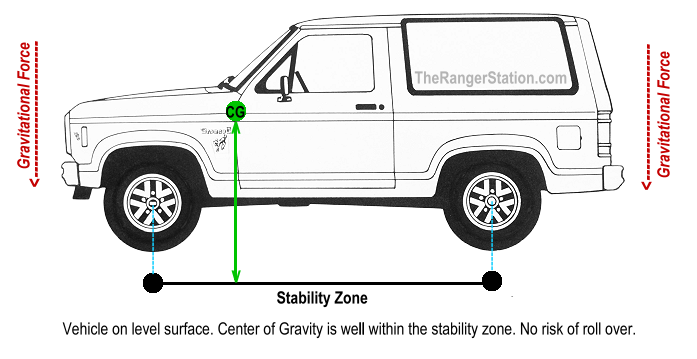
When the vehicle is level the center of gravity is well within the stability zone. No risk of a roll over.
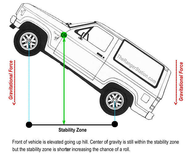
As the front of the vehicle is elevated climbing an incline, the center of gravity is within the stability zone, but the stability zone is getting shorter.
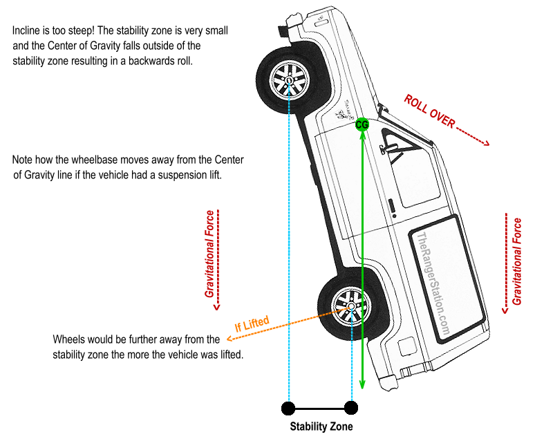
Finally, when the incline is too steep, the stability zone becomes very short, and the center of gravity falls outside of the stability zone.
Notice how steep the incline becomes before the center of gravity projection moves outside the tire support base because the stock wheels are so close to the center of gravity.
You can see that I added an orange line showing that the wheels would be further away from the vehicle if it had a suspension lift. You can see that the lift would also move the wheels further away from the green center of gravity line. If this vehicle had a suspension lift, the center of gravity would have moved outside of the stability zone well before reaching this angle. In fact, the taller the lift the further the tires would be from the center of gravity and the sooner (less angle required) the center of gravity would be outside of the stability zone. You can go back and apply the same thing to the stability zone created by the track width as well.
Calculating Rollover Angles
If you have done the work to determine where the center of gravity is located for your vehicle you have all the information you need to calculate your four rollover angles. Below are the data elements from our fictitious vehicle:
Required Data Elements to Determine Rollover Angles:
| Label | Value | Description of Data Element for Rollover Angles |
| LWB | 95 in. | Length of the Wheelbase (Axle center to axle center) |
| LTB | 65 in. | Width of the Track. (Outer tire edge to outer tire edge) |
| WBCG | 43.54 | Wheelbase Center of Gravity behind Front Axle = (1 – (WF / WT)) x LWB = WBCG |
| WTCG | 36.56 | Wheel Track Center of Gravity from the passenger side outer tire edge = (1 – (WP / WT)) x LTB = WTCG |
| HTCG | 32.80 | Your vehicles’ CG Height = HF1 + ((WRD x LWB x LWBN) / (WT x HFD)) = HTCG |
Doing The Math
Some of the following calculations use a trigonometry function called Arc Tangent (ATAN) to calculate rollover angles. Don’t let the math intimidate you. You do not need to solve these equations by hand or understand advanced trigonometry to use them.
Modern scientific calculators, smartphone calculator apps, spreadsheets like Microsoft Excel, and even Google can perform these calculations. In most cases, you simply enter the formula and the calculator returns the answer in degrees.
Example:
DSROA = DEGREES(ATAN((65 – 36.56) / 32.80))
DSROA = 40.9°
This means the vehicle would theoretically reach its driver-side rollover limit at approximately 41 degrees of side slope under static conditions.
Using Google:
Entering ‘=DEGREES(ATAN((65-36.56)/32.80))’ into the Google search bar returned a result of ‘40.93°’. Small differences in the final decimal place are normal due to rounding.
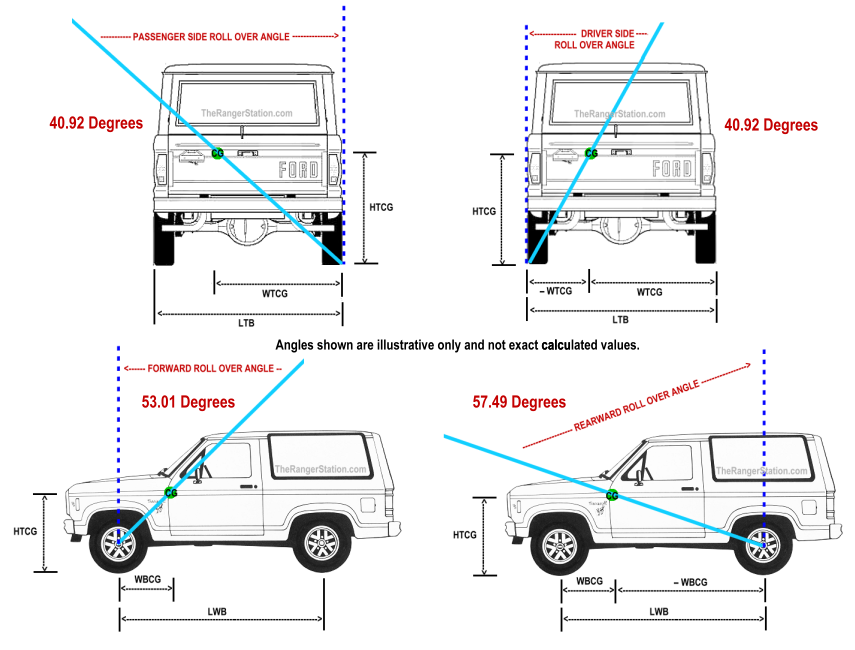
IMPORTANT NOTICE: Illustrations are for conceptual reference only and are not intended to represent exact calculated rollover angles or real-world vehicle limits.
Side Rollover Angle – WARNING!!!
This process will help you determine the center of gravity and rollover angles for your vehicle “with a reasonable degree of accuracy”.
The formulas for Driver and passenger side rollover angles DO NOT take into consideration or calculate the potential effect of the down-slope tires “rolling, sliding or tucking” under the wheels. Suspension articulation and shifting cargo can also reduce real-world rollover limits below the calculated static angle.
How much your tires may “tuck” under the wheels will depend on tire size, profile, air pressure, sidewall strength and slope of the angle.
When tires “tuck” under the wheels two physical events occur.
- The Physical Width of your vehicle’s Wheel Track is shortened. This, in combination with the angle your vehicle is on, will result in an UNKNOWN DECREASE in rollover angle!
- The Vertical Height of your vehicle’s center of gravity will be lowered. This will result in an UNKNOWN INCREASE in side rollover angle.
Driver Side Rollover Angle “DSROA”
What we will be determining is how many degrees to the left your vehicle can lean before the vertical projection of the center of gravity moves outside the support base formed by the tires.
Here is a drawing of what we are going to solve.
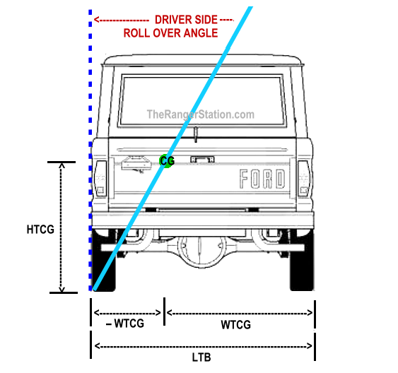
The vertical blue line represents the vertical pull of gravity on your vehicle. It intersects the angled light blue line, which runs between the outer edge of the driver side tire and the center of gravity of your vehicle.
The angle between these two lines represents the theoretical rollover threshold.
Here is the formula we will use to calculate the DSROA.
DSROA = DEGREES (ATAN ((LTB–WTCG)/HTCG))
DSROA = DEGREES (ATAN ((65–36.56)/32.80))
DSROA = DEGREES (ATAN (28.44/32.80))
DSROA = DEGREES (ATAN (0.8670731))
DSROA = 40.92 Degrees Left = Driver Side Rollover Angle
Passenger Side Rollover Angle “PSROA”
What we will be determining is how many degrees to the right you can take your vehicle before the vertical projection of the center of gravity moves outside the stability zone formed by the tires.
Here is a drawing of what we are going to solve.
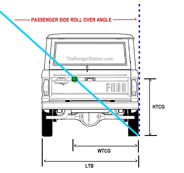
The vertical blue line represents the vertical pull of gravity on your vehicle. It intersects the angled light blue line, which runs between the outer edge of the passenger side tire and the center of gravity of your vehicle.
The angle that is formed between these two lines is the passenger side rollover angle.
And here is the formula we will use to calculate the PSROA.
PSROA = DEGREES (ATAN (WTCG/HTCG))
PSROA = DEGREES (ATAN (36.56/32.80)
PSROA = DEGREES (ATAN (1.1146341)
PSROA = 48.10 Degrees Right = Passenger Side Rollover Angle
Rearward Rollover Angle “RWROA”
What we will be determining is how many degrees to the rear you can take your vehicle before the vertical projection of the center of gravity moves outside the stability zone formed by the tires.
Here is a drawing of what we are going to solve.
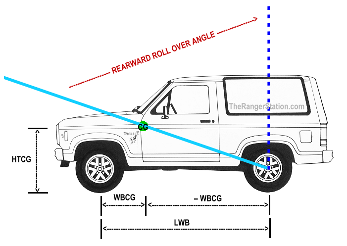
The vertical blue line represents the vertical pull of gravity on your vehicle. It intersects the angled light blue line, which runs between the centerline of the rear tire patch and the center of gravity of your vehicle.
The angle that is formed between these two lines is the rearward rollover angle.
And here is the formula we will use to calculate the RWROA.
RWROA = DEGREES (ATAN ((LWB–WBCG)/HTCG))
RWROA = DEGREES (ATAN ((95–43.54)/32.80))
RWROA = DEGREES (ATAN (51.46/32.80))
RWROA = DEGREES (ATAN (1.5689024))
RWROA = 57.49 Degrees Backward = Rearward Rollover Angle
Forward Rollover Angle “FWROA”
What we will be determining is how many degrees to the front you can take your vehicle before the vertical projection of the center of gravity moves outside the stability zone formed by the tires.
Here is a drawing of what we are going to solve.
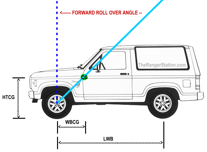
The vertical blue line represents the vertical pull of gravity on your vehicle. It intersects the angled light blue line, which runs between the centerline of the front tire patch and the center of gravity of your vehicle.
The angle that is formed between these two lines is the forward rollover angle.
And here is the formula we will use to calculate the FWROA.
FWROA = DEGREES (ATAN (WBCG/HTCG))
FWROA = DEGREES (ATAN (43.54/32.80))
FWROA = DEGREES (ATAN (1.327439))
FWROA = 53.01 Degrees Forward = Forward Rollover Angle
Summary of Rollover Angles
The rollover angles we just calculated for our fictional vehicle will look like this.
Remember, these illustrations are for conceptual reference only and are not intended to represent exact calculated rollover angles or real-world vehicle limits.
The Higher the Rollover Angle the Better!
These rollover angles are theoretical static limits calculated under controlled conditions. Real-world rollover limits are often significantly lower due to suspension movement, bouncing, shifting cargo, tire deformation, terrain irregularities, momentum, and driver input. A vehicle can roll well before reaching its calculated static rollover angle.
Think of the rollover angle as a buffer, the defined operating range in all four directions where your vehicle will remain stable and unlikely to rollover.
The greater this range (angle), the more you will be able to “safely conquer” in your vehicle.
Can you see the relationship between the physical location of the vehicle’s center of gravity and the vehicle’s stability zone (tire contact patches)?
The greater the horizontal distance between your vehicle’s center of gravity and the tire patch, the greater the rollover angle will be.
Check it out in the drawing above.
Can you see the relationship between the height of the center of gravity and each rollover angle?
The lower you can get your vehicle’s center of gravity to the ground, the greater all of your vehicle’s rollover angles will be.
Conversely, if you raise your vehicle’s center of gravity you will decrease all of your vehicle’s rollover angles.
Tuning your Vehicle’s Rollover Angles
Now that you know how to calculate the Center of Gravity and the rollover angles for your vehicle the question becomes “What to do with this information?”
Well one thing you can do is “tune” your vehicle to get the center of gravity and rollover angles more to your liking.
Here are a few of the many actions you can take to “tune” your vehicle’s center of gravity and rollover angles.
- Lengthen wheelbase and/or wheel track
- Redistribute physical weight
- Lower location of physical weight
- Remove unneeded weight
- Apply or remove cantilevered weight
Gravity Support Structure
Lengthen the wheelbase or widen the wheel track
This increases the size of the vehicle’s stability zone and generally improves rollover resistance.
Lengthening the wheelbase or widening the wheel track is something akin to putting outriggers on a canoe. They help keep it from turning over.
Weight tuning
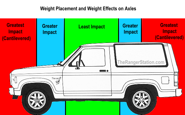
The next four examples all deal with weight. To best understand these, it would be helpful to have a general understanding of the effects of “weight placement” on your vehicle.
Where weight is placed along the wheelbase of your vehicle, or even outside the wheelbase of your vehicle, will have significant effects on the weight carried by each axle. This will affect the location of the center of gravity and your vehicle’s rollover angles.
The closer weight is located to the center of your vehicle’s wheelbase the more equally that weight will be distributed on both axles. (See Green Zone in drawing below.)
As the weight is moved closer to one of the axles, a higher percentage of weight will be placed on that axle and a smaller percentage of weight will fall over the axle farthest away. (See Blue Zones)
Things get really interesting when we hang, or cantilever weight beyond your vehicle’s wheelbase.
Cantilevered weight has the most dramatic effect on the weight distribution. (See Red Zones.)
Redistribute Physical Weight
Redistribute physical weight from one part of your vehicle to another part.
This will move the Center of Gravity in the direction you are moving the weight and away from the location where the weight came from.
This can improve or reduce rollover angles depending on where the weight is moved.
Lower the Physical Location of Weight
Any time existing weight can be lowered you will lower the center of gravity of your vehicle.
A lower center of gravity will create greater rollover angles.
Remove Unneeded Weight
Removing unneeded weight will affect the height of your vehicle’s center of gravity.
However, be aware! Removing weight can either raise or lower the height of your vehicle’s center of gravity.
Weight removed that was BELOW the original Height of the center of gravity will cause the new center of gravity to rise. (Think removing your skid plates)
If the center of gravity goes up, the rollover angles will decrease.
Weight removed that was ABOVE the originally height of the center of gravity will result in a new lower center of gravity.
If the center of gravity goes down, the rollover angles will increase.
Apply or Remove Cantilevered Weight
Yes, this is the real interesting weight placement.
Any weight hanging in front of the front axle or behind the rear axle is called cantilevered weight.
Cantilevered weight has a “force multiplying” effect on the weight distribution over your axles and on the location of your vehicle’s center of gravity.
There are two unique physical effects of cantilevered weight.
- Cantilevered weight will increase the weight on the nearest axle by an amount GREATER than the actual weight being added.
- Cantilevered weight will cause a fractional DECREASE in the weight on the axle farthest away.
The effects of cantilevered weight on your vehicle can be calculated prior to actually adding the weight.
Here are the data elements you will need and the formulas to calculate the effects of cantilevered weight.
| Data Elements Required to Calculate Effects of Cantilevered Weight | |
| ADDW | Weight of the object you are going to place in a cantilevered position |
| CANTD | The distance from the axle center to the weight you are adding |
| LWB | The length of your vehicle’s Wheelbase |
In this example we will add a winch and mounting plate to the front of a vehicle.
ADDW = 150 lbs. = Weight of winch and mounting plate
CANTD = 26 inches = Distance to front axle center from center of the winch plate
LWB = 95 inches = Length of the vehicle’s Wheelbase
Here is a formula that can be used to determine the weight that will be added to the front axle as a result of mounting a 150 lbs. winch on the front bumper.
(ADDW x CANTD) / LWB + ADDW = Weight added to front axle
(150 x 26) / 95 + 150 =
(3900 / 95) + 150 =
41.05 + 150 = 191.05 lbs. added to front axle
And here is the formula to determine the how much weight will be removed from the rear axle as a result of mounting this winch on the front bumper.
(AddW x CantD) / LWB = (Weight removed from Rear Axle)
(150 x 26) / 95 =
(3900 / 95) = 41.05 lbs. of weight removed from rear axle
In summary, the winch and mounting plate added a total of 150 lbs. of new weight to the vehicle. However, because of this weight’s cantilevered placement the effects on the front and rear axle weights are far greater than 150 lbs.
- Front axle weight goes up by 191 lbs. That is 27% more weight than the winch and mounting plate actually weigh.
- The rear axle received a weight reduction of 41.05 lbs. because of the leverage effect of the cantilevered weight.
- The vehicle’s Wheelbase Center of Gravity was also changed. It was shifted forward toward the front axle by a multiple of the weight added.
If you care to you can go back and recalculate the new WBCG by adding and subtracting these weights from the front, back and total of our example vehicle. You will see that the Wheelbase Center of Gravity has indeed been moved forward as a result of mounting the winch on the front bumper.
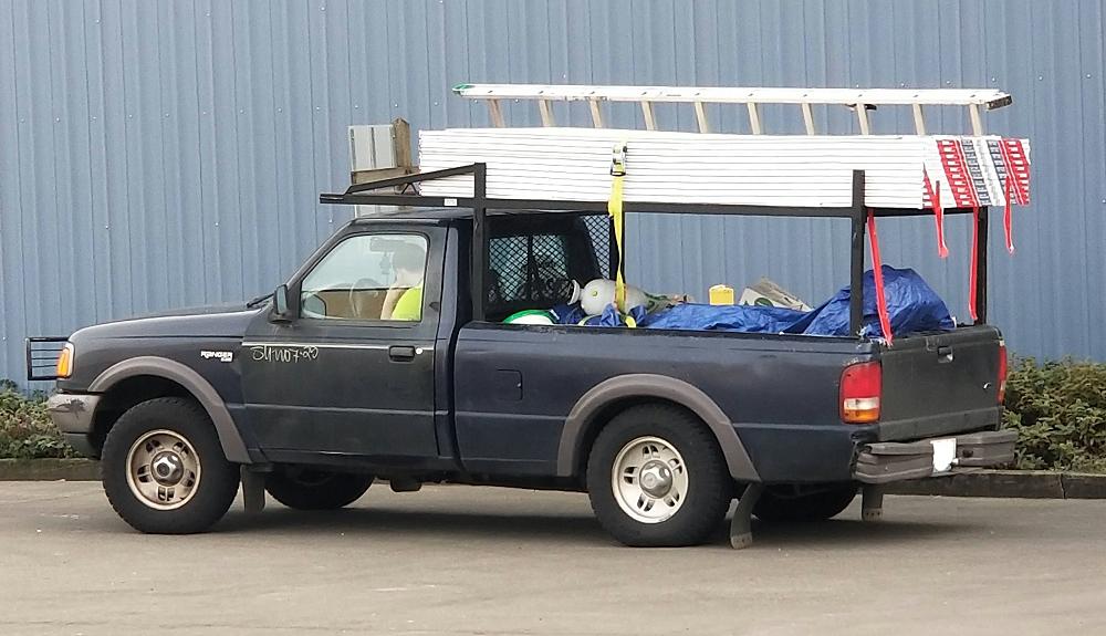
Center of Gravity Doesn’t Just Apply to Off-Road Driving
Although we’ve focused heavily on off-road and overlanding applications, center of gravity affects every vehicle on the road—including those driven at highway speeds.
This 1993–1997 Ford Ranger 2WD (shown below) has a payload capacity of roughly 1,250 to 1,650 lbs. (including the driver). The bed rack is loaded with ten sheets of drywall and an aluminum extension ladder.
A single 1/2-inch sheet of drywall weighs about 51–58 lbs., meaning the load on the rack adds at least 510 to 580 lbs. carried above the bed line. That elevated weight significantly raises the vehicle’s center of gravity.
At highway speeds, the effect of that higher center of gravity becomes most noticeable in corners. As the truck enters a turn, lateral acceleration acts through the raised center of gravity, creating a roll force that shifts the load onto the outside tires across the track width. The higher the load is carried, the greater the body roll and the closer the vehicle gets to the point where the center of gravity can move outside the tire contact patch’s support base increasing the chance of the vehicle rolling over or the driver losing control.
Personal Experiences
During my decades as an off-roader I have seen some scary situations, close calls, and roll overs. It seemed evident during those times that the person or people involved didn’t understand the vehicles center of gravity and the effect it was having on the vehicle. Or perhaps they were too caught up in the moment to think about it. Sometimes people know there’s a risk of a rollover while trying to navigate an obstacle, pick their line to tackle it, and the obstacle wins. Or the vehicle loses traction and slides off not giving the driver any control over it. Sometimes the people watching can predict you’re going to roll over before you realize it’s about to happen. And sometimes there’s just an unexpected change in the terrain that catches you off guard. But understanding the information in this page and the effects it has on your vehicle can help you get through those situations.
It helps if you can avoid those situations in the first place.
I once saw a Ford Ranger climb a hill, not make it, and then decide to turn around on the side of the hill instead of backing up. Someone was hanging onto the corner of the bed to keep it from rolling over. After reading this article, we know that the vehicle was stable because of the stability zone created by the length of its wheelbase. But once it tried to turn around, the stability zone was now it’s track width which was much small and the center of gravity was moving to the edge of that stability zone.
I also saw a Toyota pickup with a tall lift but still somewhat narrow tires on narrow stock axles go racing down a straight away on a tough truck course and I knew watching it that the truck was going to roll over when it hit the first turn, and it did. Why? High center of gravity, a narrow track width to stabilize it, and momentum. The faster he went the more probably it was that he was going to flip.
I’ve also seen Bronco II’s climb steep trails, hit a bump, and watched the front tires come off the ground. The more lift it had, the more likely it seemed to be that it was going to lift the front. Especially if it had a lot of weight mounted above the rear bumper.
Understanding your vehicles center of gravity will make you a better off-roader and safer overlander.
Final Thoughts
Off-road stability is not determined by any single number, modification, or formula. It is the result of how weight, suspension, traction, terrain, momentum, and driver input interact in constantly changing conditions.
A vehicle with excellent static rollover numbers can still become unstable in the real world if cargo shifts, suspension unloads, tires regain traction suddenly, or momentum creates forces beyond the available stability margin.
Understanding center of gravity is ultimately about understanding consequences. Every lift, roof rack, spare tire carrier, fuel can, suspension change, and cargo decision affects how a vehicle behaves when conditions become difficult.
The goal is not to drive at the edge of a vehicle’s rollover limits. The goal is to understand where those limits exist — and maintain enough margin to avoid reaching them in the first place.
Excel Worksheet
Below is a link for an Excel worksheet that you can download and open in Excel or LibreOffice to calculate your vehicle’s center of gravity and rollover angles.
If you click the link, the worksheet will open in read-only mode. You’ll need to save it to your computer before entering your own values.
Only change the numbers in the Light Blue boxes in the first section. Make sure you replace all of those values with your own numbers.
About The Author
Jim Oaks is the founder of TheRangerStation.com, the longest-running Ford Ranger resource online since 1999. With over 25 years of hands-on experience building and modifying Ford Rangers — including magazine-featured builds like Project Transformer — Jim has become one of the most trusted authorities in the Ford Ranger off-road and enthusiast space.
Since launching TheRangerStation.com, Jim has documented thousands of real-world Ranger builds, technical repairs, drivetrain swaps, suspension modifications, and off-road adventures contributed by owners worldwide. TheRangerStation.com has been referenced in print, video and online by enthusiasts, mechanics, and off-road builders looking for practical, and experience-based information.