
Submitted By: matteo_g
I recently investigated to figure out why the horn on a vehicle with the Smart Junction Box (SJB) has such a delay when being activated. There is a circuit on the Low Current Board (LCB) in the SJB that drives a relay that actually turns on the horn itself. This circuit can be driven from at least a couple sources:
1) the horn switch on the steering wheel of course, and:
2) the OEM security system and keyless entry.
The horn switch from the steering wheel grounds an input to a microcontroller on the LCB. Unfortunately, the designers introduced a delay between when you press the horn switch and when the horn relay actually turns on. So as a result, you can’t gently pound the on the horn to get a couple short “beeps” without making it seem like your having road rage against the driver in front of you. It also doesn’t work well when you’re trying to let the cute chica on the sidewalk know that she’s hot!
Below is the process I went through to make this modification. The Ford part number of the SJB on my 2007 Ranger Sport is 7L5T-14B476-CG. This procedure probably applies to most, if not all of the SJBs with different letter suffixes, although I am not certain if it applies to SJBs without keyless entry; I suspect that this method does apply since it’s unlikely the microcontroller & relay circuit got eliminated in systems without keyless entry, even if there is only one source to turn on the horn.
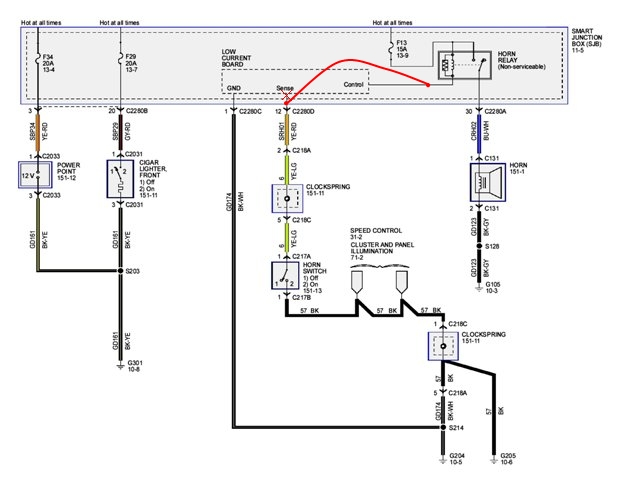
Step 1 – Wiring diagram and a technical description of the modification itself:
This is wiring diagram for the circuit being modified. The change is very simple. The connection to the LCB sense input gets disconnected, and a wire gets run from the horn switch itself to the relay that turns on the horn. Because the output of the LCB that turns on the horn relay is an open-collector/drain type circuit, grounding this output to turn on the relay from a different source (the steering wheel horn switch) is a safe thing to do; it’s called a “wire-OR” circuit in electronic terms. Since the relay’s coil circuit is low current, there is no issue with overloading the steering wheel horn switch and its wiring. It’s a small amount of current. Beyond this, disconnecting and leaving the horn switch sense input floating is okay because this input has a pull-up resistor at the microcontroller input where it leads, so the horn won’t be turning on when you don’t want it to. Lastly, this wiring still allows the output from the LCB to turn on the horn whenever it needs to for the keyless entry and security system.
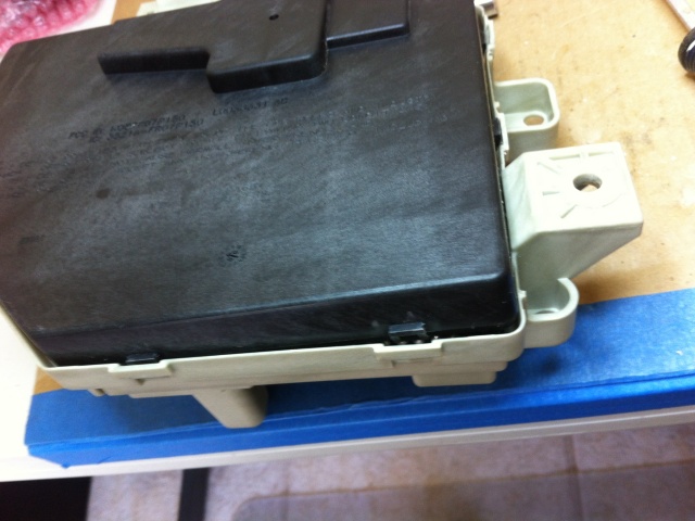
Step 2 – Locate the Smart Junction Box in the passenger side kick:
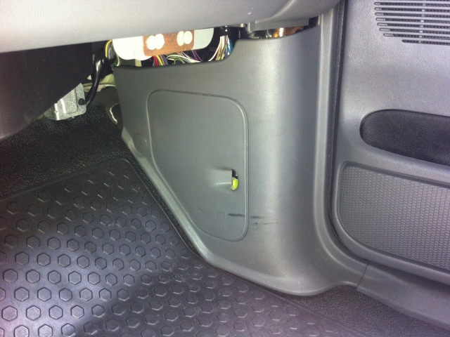
Step 3 – Remove the entire kick panel covering the SJB:
The access panel door is not large enough through which to do this job. The entire kick panel must be removed. This photo shows the two pins that hold it in. Two ends of the panel are tucked under two adjacent panels, one on the door threshold and one on the hinge jamb.

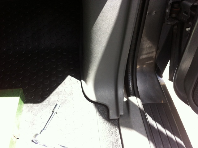
To remove the panel, first take out the large gray retaining pin in the back, slide the foot of the panel out from under the door threshold trim, then slide the entire panel down to get it out from the door jamb panel (not shown here). Sliding the panel down also disengages it from the hidden white retaining pin that’s underneath along the door jamb. This white pin can then be removed and put back into the panel before re-installation later on (as shown in the above photo).
Step 5: Disconnect all the plugs to the SJB and remove the three 10mm hex bolts to completely remove it from the vehicle
The plugs have special release handles that pop out the plugs. Unlatch them from one end, and swing them across, and the plug pops out. Leave the handle where it is because it will swing itself back across the other when you put the plug back in later on.

Step 6 – Dissemble the SJB:
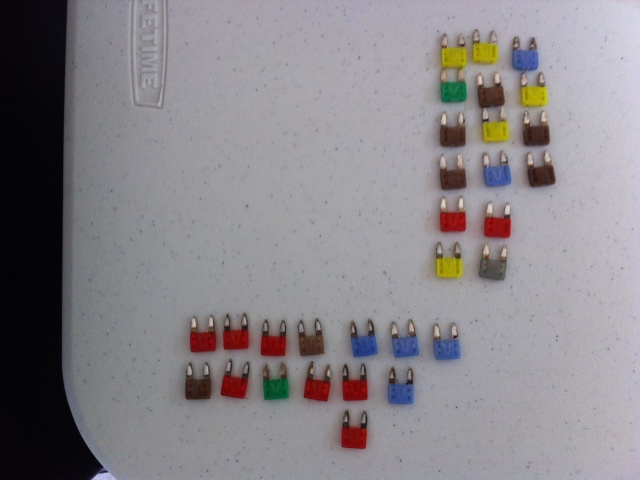
This is your starting point. Take a picture of yours so you have a record of where all the fuses go.
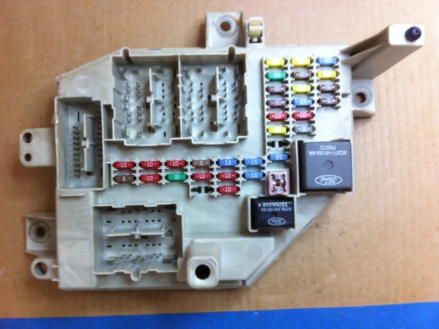
Remove all the fuses and arrange them for reinstallation later on. Also remove the two plug-in relays (window and accessories) and the big 30A fuse (pink one).
Pop the cover off the back by starting in this corner. The plastic is kinda brittle, so be careful. Carefully use a couple screwdrivers to gently release the catches and work your way around the back cover.
Once the back cover is off, when you turn over the SJB the entire board assembly will slide out.

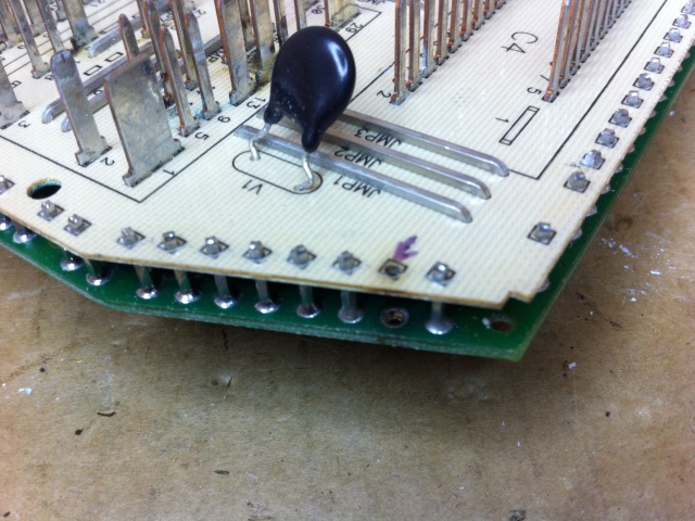
Step 7 – Locate the points where the modification will be done:
These are the points to be worked on.

This is the horn relay itself and its associated coil bleed resistor. (Nothing to be done here, so this is just FYI.)

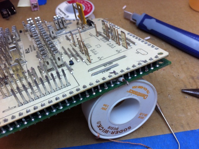
Step 8 –Remove the pin that connects the horn switch to the sense input on the LCB:
All of the pins that sandwich the various SJB boards together are soldered on both ends to create the connections back and forth. Remove the pin shown since we want to disconnect the horn switch connection from the steering wheel from the LCB sense input. Use a very hot, large tip soldering iron to do this if you have one. I used my Weller with the temperature turned up all the way and added more solder for good heat transfer, and I was able to keep both solder joints melted while I pushed out the pin with another metal pin (paper clip or a pick).
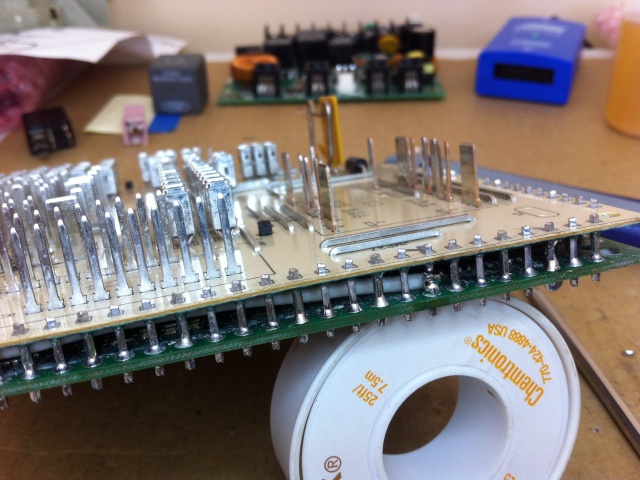
Step 9 –Thread a #18 wire inside the board sandwich to both locations:
The plastic housing for the SJB fits around the board sandwich very tightly. Therefore, it’s best to run the jumper wire that much be installed inside the board sandwich, so it doesn’t interfere with the housing.
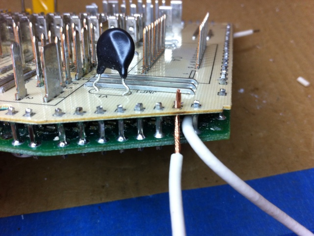
Step 10 –Solder the white wire to the horn switch input pin connection:

Step 11 – Prepare and solder the connection on the relay coil connection pin:
There is not a lot of room in the board sandwich to push back in any extra slack in the wire. So, strip the end as close to the pin as possible, tin it with solder, and make a small hook that you can wrap around the pin.
Solder the hooked connection to the pin.
Step 12 – Reassemble and reinstall:
You’re done! Reassemble the SJB in the reverse order, replacing all the fuses and relays to their exact same locations, and snap on the back cover. Put it back in your vehicle, go for a test drive, and toot (nicely) at the pretty girls!
See She Original Post
You can see the original discussion HERE.
Related Articles
Ford Ranger Short Burst Horn Modification
Last updated:
About The Author
Jim Oaks is the founder of TheRangerStation.com, the longest-running Ford Ranger resource online since 1999. With over 25 years of hands-on experience building and modifying Ford Rangers — including magazine-featured builds like Project Transformer — Jim has become one of the most trusted authorities in the Ford Ranger off-road and enthusiast space.
Since launching TheRangerStation.com, Jim has documented thousands of real-world Ranger builds, technical repairs, drivetrain swaps, suspension modifications, and off-road adventures contributed by owners worldwide. TheRangerStation.com has been referenced in print, video and online by enthusiasts, mechanics, and off-road builders looking for practical, and experience-based information.