
Introduction
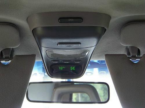
The Ford Explorer overhead console is a popular conversion on the 1993-2011 Ford Ranger. Here’s how to install one in your Ford Ranger.
Index:
Removing The Console
Mounting The Console
Running The Wires
Figuring Out The Wires
Plug Labels
Tapping The Wires
2004 & Newer Wiring Differences
Temperature Sensor
Compass Adjustments/Calibration
Rear View Mirror Wiring
Lighted Visor Mirror Wiring
One day in July I went to the salvage yard to get a new right front axle shaft for my Ranger. I ended up getting an overhead console out of the donor Explorer while I was there. In fact, when it was all said and done, I got the overhead console, both visors with lighted mirrors, the auto dimming rear view mirror and the center console between the seats.
I began searching our forums to find information for the wiring. As things usually work out, I ended up with a harness with wires that didn’t match the colors/info I found on line. Some were the same. Some were different.
Here is a breakdown of what I did.
Removing the console is fairly easy. You need to open up the section where the garage door opener goes and remove the (2) screws. Then pull down on the console to remove it from the mounting plate. It has (2) metal clips that are holding it in place near the front (windshield end) of the console. Once you have it loose you can unplug the harness and remove the console. Then remove the (2) screws holding the mounting plate to the roof and take the mounting plate as well.
To simplify things, I removed the visors and trim so I could pull the headliner down to get at the wiring.
I found that the wire loom also contained a power wire going to each visor as well as wiring that went down to the dimming rear view mirror. I decided to grab it all since it was going to end up in the crusher anyway.
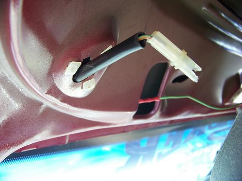
The harness runs down the driver side windshield post and then down through the dash in a gap near the windshield. I looked under the dash near the driver side kick panel to see if I could unplug it, but some of the wires in the loom didn’t all go in to the plug so I just cut it down there. I figured that would give me a good open but concealed area to extend the harness as needed.
The other part you need is the temperature sensor. Very important. It’s on the front of the core support just to the passenger side of the radiator. Below is a picture of mine.
Mounting the console bracket is the hardest part of this installation. I took a profile shot of where my bracket is mounted to hopefully give you an idea of where yours should be.
Console bracket mounted to show you for reference. The bracket should come up to the lip of the cabs roof.
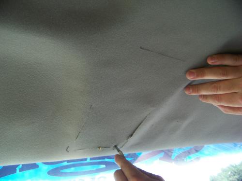
Here the headliner is being cut after using the bracket as a template.
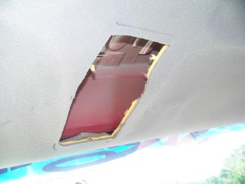
Here’s the section cut out.
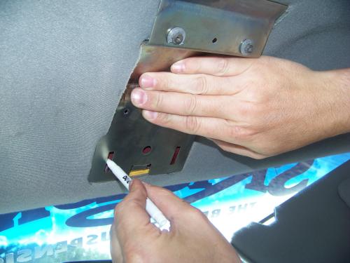
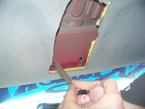
Here I placed the bracket back up to mark these slot holes. You have to cut these in for the console to fit. See the screws in the bracket? Someone tried to remove the console from the headliner without unscrewing it. I was able to remove the pieces of plastic and put a washer behind the screws to hold the console in place when I screwed it up to the bracket.
I cut a small guide hole at the top and bottom of the area I traced for the slots. Then I used a larger drill bit to make the holes larger. A small saw blade was used to open it up.
Then I just filed the holes to clean them up.
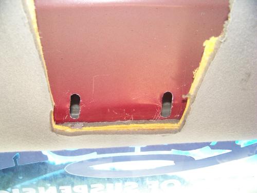
The overhead console snaps into the front of the bracket and then has two screws at the rear of the bracket. You need these slots to allow room for the consoles metal clips when they snap in to the slots in the bracket. If you do not do this, the console will not fit up against the headliner.
NOTE: You may have to lengthen these slots to get the console to fit right. Snap the console into the bracket and put it up in place to make sure it will sit flush to the headliner. Make sure it fits right and make adjustments before drilling the two remaining bracket holes.
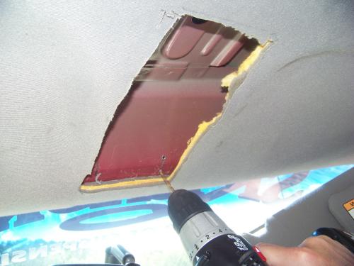
Once you have your front slots made, you need to drill two holes to screw the bracket to the roof of the cab.
CAUTION: You have an inside and outside layer of sheetmetal. Don’t drill through both layers. Duh!
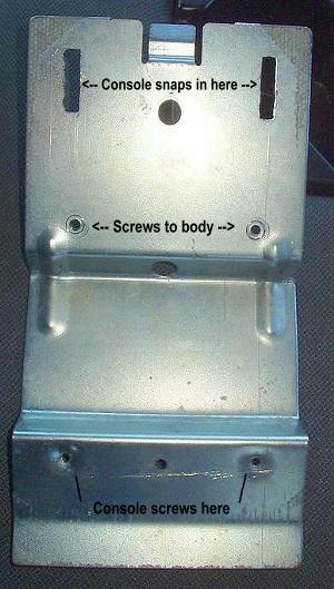
The mounting bracket should not be attached to the roof using the screw holes noted in the picture above (<– Screws to body –>). The front of the console then snaps on to the bracket. Two screws go through the holes inside the garage door opener compartment and attached the rear half of the console to the bracket using the holes in the picture above (Console screws here).
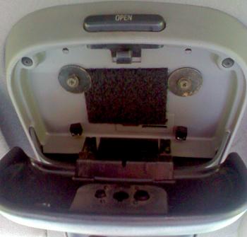
Not a good picture, but here’s the screws that hold up the rear of the console. They’re normally recessed into the console, but as I mentioned earlier, the plastic around the screw holes was broke (looks like someone tried to pull it down), so I had to use a washer under each screw to hold it up.
You will need to remove the dome light, pull out the radio and remove the A pillar cover from the drivers windshield pillar. It just pulls straight off and snaps back on.
A couple wires will just run to your dome light. You’ll need to run some of the console wires along the A pillar, down it to the dashboard, and through a small gap at the top of the dashboard on the side. You probably cut the wires just under the dash on the Explorer, so from here you’ll have to extend the necessary wires to their proper location. Some will go through the firewall to the front of the truck, and some will go up behind the radio. The next few sections will tell you which wires go where.
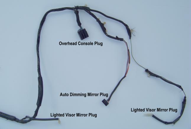
As I said, my harness doesn’t exactly match that of others who have posted information online about performing this swap. Here is a break down of what I found with mine.
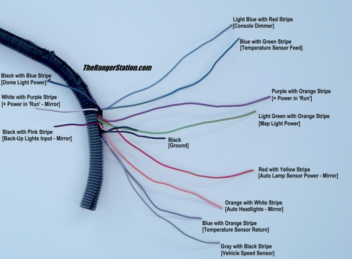
After taking that picture I decided to separate the harness because I wasn’t going to use the auto dimming mirror. I decided to use the picture anyway for anyone that may be looking for information on the other wires.
Here is a photo of the console plug. I numbered each pin so I could identify the wires for you.
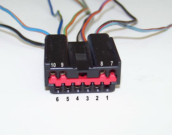
| Pin Number | Color | Purpose |
| 1 | N/A | Not Used |
| 2 | Black | Ground |
| 3 | Purple with Orange Stripe | Power (Hot in Run) |
| 4 | Gray with Black Stripe | Speed Sensor |
| 5 | Light Green with Orange Stripe | Map Light Input |
| 6 | Black with Light Blue Stripe | Courtesy (Dome) Light Input |
| 7 | N/A | Not Used |
| 8 | Light Blue with Red Stripe | Instrument Light Input |
| 9 | Blue with Light Green Stripe | Temperature Sensor Feed |
| 10 | Light Blue with Orange Stripe | Temperature Sensor Return |
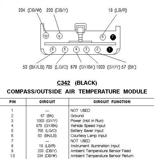
Some (probably most) of you may have ended up with a wiring harness that used Blue/White and Blue/Yellow wires for the temperature sensor. If so, use the description below:
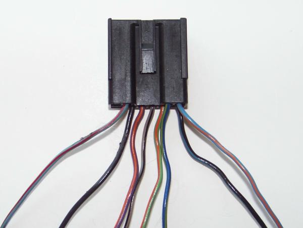
Just another view of the wire colors on my consoles harness
Most of your connections can be made with wire taps:
Console Power: The Purple with Orange stripe wire (Pin #3) provides the console it’s power. Your wire may be Yellow and Gray. Run this to the Yellow with Black stripe wire going to your radio. This provides fused ignition power.
Ground: The black wire (Pin #2) is the ground wire. Ground accordingly to the vehicles body.
Dome Lights:The Black with Light Blue stripe wire (Pin #6) can be connected at your factory dome lamp. The Black with Light Blue stripe wire is your dome light wire and is hot when the door is open or you turn on your dome light switch. Tap your harnesses Black with Light Blue stripe wire into the existing wire.
Map Lights:The Light Green & Orange wire (Pin #5) is for your map lights. Tap them into your existing Light Green & Orange wire in your head liner at the dome light. If you don’t have a map light now that can be switched on and off at the switch, all you really need to know is that the wire is hot at all times. All you need is to run a hot wire to the Light Green & Orange wire to power your map lights.
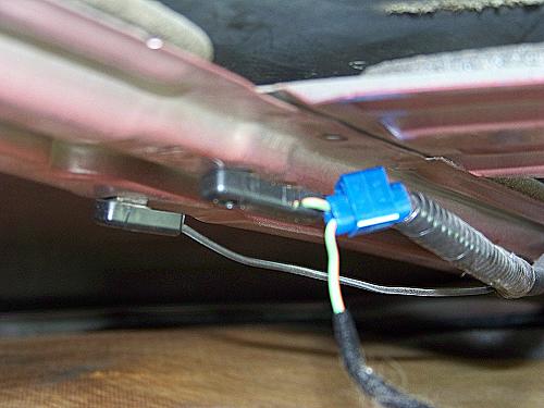
Photo of Light Green & Orange wire tapped into the existing Light Green & Orange wire at the dome light connection under the headliner.
Instrument Light Dimmer: The Light Blue with Red stripe wire (Pin #8) is used to dim the display of the console with the dash lights. Look behind the factory radio and you’ll find another Light Blue & Red stripe wire to tap in to.
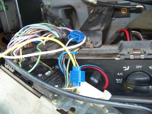
Here are the taps for the Light Blue with Red stripe wire (Dimming) and wire (Power For Console)
Vehicle Speed Sensor (VSS): The Gray with Black stripe wire (Pin #4) controls how increases in temperature are processed. This keeps the engine heat from causing artificial spikes in temperature. Basically, the console does not allow the temperature to increase unless it sees the truck in motion for a while to make sure the engine heat has been dispersed. If you don’t hook up this wire, your console will appear to freeze its temperature display and not show temperature changes.
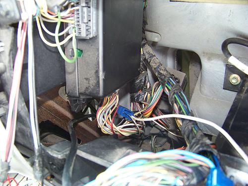
The black box in the photo is the GEM (Generic Electronic Module) inside the dash just to the left of the factory radio. I tapped into the Gray Wire with Black stripe coming from the bottom of the GEM and connected it to the Gray Wire with Black stripe in the consoles harness.
If you have a newer generation Ranger, you probably have two connectors on the bottom of your GEM. One is black and one is gray. You want the wire coming from the black connector closest to you on the bottom.
2004 & Newer Ranger Differences:
There are a few differences for 2004+ as described by ‘rwenzing’ from our forums:
Console Power (Explorer Yellow/Gray at console): 2003 and older Ranger’s use the Yellow/Black wire at the radio harness. 2004 and newer Ranger’s use the Black/Pink wire at the radio harness.
Speed Sensor Input (Explorer Gray/Black at console): 2003 and older Ranger’s use the Gray/Black wire at the GEM. 2004 and newer Ranger’s use the Gray/Black wire at the Smart Junction Box (brown connector).
Map Light Power (Explorer Lt. Green/Orange at console): 2003 and older Ranger’s use the Lt. Green/Orange wire at the dome light. 2004 and newer Ranger’s use the Lt. Green/Orange wire at the dimmer module.
Temperature Sensor Feed: The Blue with Light Green Stripe wire (Pin #9) is the Temperature Feed wire and attaches to the same color wire on your temperature sensor plug.
Temperature Sensor Return: The Light Blue with Orange Stripe wire (Pin #10) is the Temperature Sensor Return wire and attaches to the same color wire on your temperature sensor plug.
Other Wire Colors: Your temperature sensor wires may be Light Blue with White stripe and Light Blue with Yellow stripe.
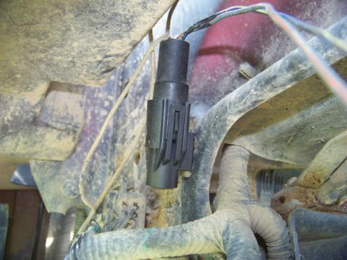
Here is the Temperature Sensor mounted to the front of the Ranger to the lower right of the radiator.
There are two possible adjustments to the compass: Variation and Calibration.
In order to perform the Variation Adjustment:
1) Determine which zone of the country you are in from the map below.
2) Press and hold the MODE button until the VAR indicator appears in the display (Approximately 4-seconds)
3) Release the MODE button. The display will now show the current zone number that is stored in the compass.
4) Press the MODE button repeatedly (or press and hold in) until the desired zone number appears in the display (once it reaches 15, the next press of the button will set it to 1).
5) Release the MODE button when the desired zone number is displayed.
After approximately three seconds the display will flash all segments and then return to normal operation.
If the compass seems inaccurate, and the Variation Adjustment procedure did not correct the problem, perform the following Calibration Procedure.
1) Find an open area that is free from steel structures and high voltage lines. An open parking lot is a good example.
2) Press and hold the MODE button until the CAL indicator appears in the display (approximately 8-seconds).
NOTE: After approximately 4 seconds, the VAR indicator will light. Continue holding the MODE button until the CAL indicator appears. If you release the MODE button after the VAR indicator appears, but before the CAL indicator appears, the compass will be in the Variation Adjustment mode.
3) Release the MODE button.
4) Once the CAL indicator has appeared, drive the vehicle slowly (less than 3 mph) in 360-degree circles until the CAL indicator turns off. This will happen with 2 to 3 complete circles.
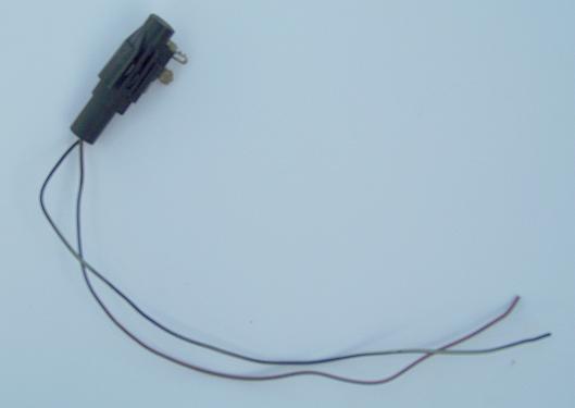
If you also grabbed the auto dimming mirror out of the Explorer, here’s some information I figured out on it as well. I chose not to install the mirror, so don’t email me and ask me questions on installing it.
The Mirror I got is a Gentex-104 that has 5-wires in the plug. They are:
| Color | Purpose |
| Red with Yellow Stripe | Auto Lamp Sensor Power |
| Orange with White Stripe | Auto Headlights |
| Black | Ground |
| Black with Pink Stripe | Back Up Lamp Input |
| White with Purple Stripe | Power (Hot in Run) |
The lights in the mirror use the Light Green and Orange wire for power. See above for Map Lights.
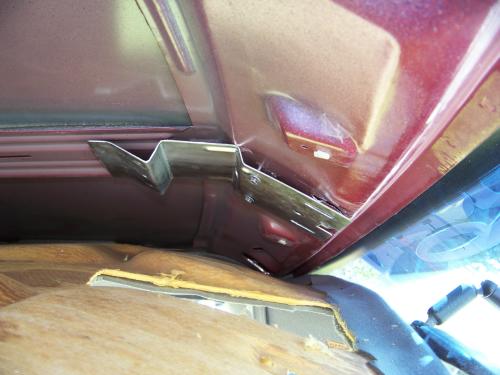
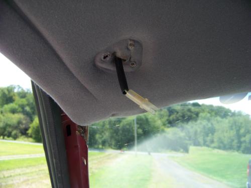
Run the wire for your visor mirror lights as shown. Note the plastic pieces where the visor screws in to the body. I grounded a small wire with grommets, one to the body and the visor screw went through the other end. This was needed to ground it so the lights would light. If you put all three of your screws in to the plastic pieces, the lights won’t be grounded and won’t work.
Run your wire through the headliner and plug in to the visor
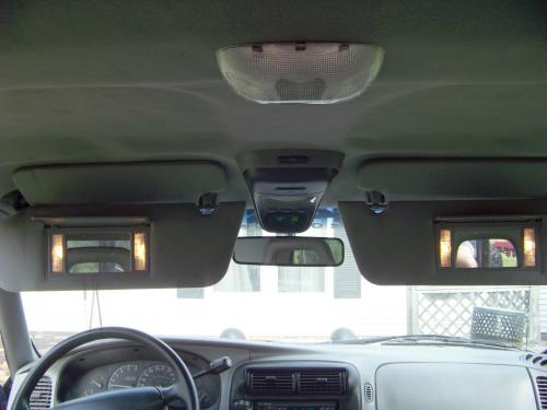
Here’s what it all looks like when it’s done.
Related Articles
1995-2001 Ford Explorer Center Console Removal
Explorer Center Console Upgrade
Remove / Install 2002-2005 Ford Explorer Center Console
How To Remove The Center (Short) Console
Ford Explorer Full Length Console Install
Ford Explorer Console Information Center
Last Updated:
About The Author
Jim Oaks is the founder of TheRangerStation.com, the longest-running Ford Ranger resource online since 1999. With over 25 years of hands-on experience building and modifying Ford Rangers — including magazine-featured builds like Project Transformer — Jim has become one of the most trusted authorities in the Ford Ranger off-road and enthusiast space.
Since launching TheRangerStation.com, Jim has documented thousands of real-world Ranger builds, technical repairs, drivetrain swaps, suspension modifications, and off-road adventures contributed by owners worldwide. TheRangerStation.com has been referenced in print, video and online by enthusiasts, mechanics, and off-road builders looking for practical, and experience-based information.