
Introduction
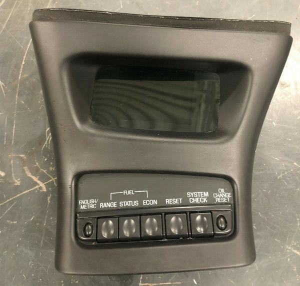
The 1995-2001 Ford Explorer center console came with an option Information Center. This article provides information on how it operates and how to install it.
Principles of Operation
Display Dimming
The dimming of the indicator display is controlled by the pulse width dimmer module. The voltage on Pin 2 controls the brightness of the message center display. When the exterior lamps are off, this voltage will be zero volts and the message center display will be at maximum brightness. When the exterior lamps are on, this voltage will be controlled by the pulse width dimmer module and will be between 2.5 volts and battery voltage. The message center display will be brighter as this voltage approaches battery voltage. If there is a warning on the message center display, the display will not dim to its lowest level.
When the headlamps (13008) or parking lamps are OFF, the display of the message center indicator will be maximum brightness and the labels for the center five switches of the message center switch module will not be illuminated.
When the headlamps or parking lamps are ON, the brightness of the display of the message center indicator and the labels for the center five switches of the message center switch module will be controlled by the pulse width dimmer module.
For additional information, refer to «Section 413-00».
English/Metric Mode
The ENGLISH/METRIC switch controls the display mode for both the message center indicator and the electronic automatic temperature control. A press of the ENGLISH/METRIC switch will change both displays between English mode and metric mode.
Vehicle Speed Signal
The vehicle speed signal is generated by the rear anti-lock brake sensor and sent to the 4-wheel anti-lock brake system (4WABS) module. The 4WABS module sends the vehicle speed signal via circuit 679 (GY/BK) to all systems which require a vehicle speed signal input.
Fuel Computer — Range
The RANGE feature has two displays: the distance that can be traveled before refueling, and the distance that was traveled since the last trip odometer reset. The RANGE switch will change the message center indicator between the two displays.
The RANGE (distance to empty) feature is calculated using the fuel flow signal from the powertrain control module (PCM) (12A650), the speed signal from the 4WABS module and the fuel level signal from the fuel level sender.
The fuel flow and speed signals are used to calculate a running average fuel economy (RAFE), which is multiplied by the fuel remaining to give the range.
RAFE is not the same number as the Average Fuel Economy displayed by the message center indicator.
RAFE is based on the past driving history and can only be reset by disconnecting the battery.
When the range decreases to 80 km (50 mile) to empty, the message center will display the LOW FUEL LEVEL warning.
With a fuel tank (9002) full of fuel (160 ohm signal from fuel sender) and after a battery disconnect, the RANGE should be approximately 644 km (400 miles) to empty.
The RANGE (trip odometer) feature is calculated using the speed signal from the 4WABS module. It can be reset to zero by pressing the reset switch while the trip odometer is displayed on the message center.
Fuel Computer — Status
The STATUS feature has two displays: Fuel-to-Empty and Fuel-Used. The STATUS switch will change the message center indicator between the two displays.
The fuel-to-empty calculation is achieved using the fuel level signal from the fuel level sender.
The fuel-used feature is calculated using the fuel flow signal from the PCM and can be reset to zero by pressing the RESET switch while the fuel-used feature is displayed on the message center.
Fuel Computer — Economy
The economy (ECON) feature has two displays: average and instant.
Depressing the ECON switch changes the message center indicator between both displays.
The economy is calculated using the fuel flow signal from the powertrain control module and the speed signal from the 4WABS module.
The average fuel economy feature can be reset by pressing the RESET switch while the average fuel economy feature is displayed on the message center indicator.
System Check and Warnings
The SYSTEM CHECK feature cycles the message center indicator through a status of each system being monitored.
l For each of the monitored systems, the message center indicator will indicate either an OK message or a warning message for two seconds.
l At normal conclusion of the system check sequence, the message center indicator will display all active warnings or the last feature displayed before entering the SYSTEM CHECK mode.
l System warnings alert the driver to possible concerns or malfunctions in the vehicle operating systems.
l There are 7 warning messages which can be displayed for two seconds by the message center indicator to show the status of the monitored systems.
l When a warning occurs, the warning message is displayed and a one-second tone sounds. The warning message will appear at a brighter level if the message center indicator is dimmed.
l In the event of a multiple warning situation, the message center indicator will cycle the display to show all warnings by displaying each warning message for four seconds.
l To display the operator selectable features of the message center indicator while a warning is displayed, the warning message may be removed from the message center indicator display by pressing the RESET switch. The message center indicator will display the last selected feature if there are no more warning messages.
l This allows operation of all functions of the message center indicator after pressing the RESET switch and clearing the warning message.
Warning messages which have been reset will either reappear on the display in 10 minutes from the reset or will not reappear until an ignition switch OFF-RUN cycle.
If warning messages reappear it is a reminder that these warning conditions still exist. Warnings may be repeatedly reset. All warning messages will reappear after an entire SYSTEM CHECK sequence has been completed.
Charging System Warning (CHECK CHARGING SYSTEM)
This warning message is displayed when the electrical system is not maintaining correct voltage at the message center indicator. There will be a few seconds delay before the warning is displayed or removed.
Engine Coolant Temperature Warning (CHECK ENGINE TEMP)
This warning message is displayed when the engine coolant is overheating.
The message center indicator senses the voltage level on Circuit 39 (RD/WH) (C2008-8 to the message center indicator).
If that voltage is greater than approximately 2.7 volts, at a battery voltage of 13.5 volts there will be no warning. If it is less than approximately 2.7 volts, at a battery voltage of 13.5 volts then the warning will be displayed.
The message center indicator filters this input; therefore, there will be a few seconds delay before the warning is displayed or removed.
Fuel Level Warning (LOW FUEL LEVEL)
This warning message is displayed when there is approximately 80 km (50 mile) or less left before the vehicle runs out of fuel.
Oil Level Warning (LOW OIL LEVEL)
This warning message is displayed when the engine oil level is low.
When the engine oil level is normal, the input to the message center indicator will be an open circuit.
When the engine oil level is low, the low oil level sensor (6C624) will close, grounding the input to the message center indicator and the warning will be displayed during the next ignition cycle of OFF to RUN. This low oil level sensor is only monitored when the ignition switch (11572) is OFF.
There is a delay of up to 12 minutes in this monitoring in order to allow the oil to drain back into the oil pan (6675) and reach the correct level.
Oil Life Warning (CHANGE OIL SOON or OIL CHANGE REQUIRED)
If the connection to the oil temperature sensor is open circuit or shorted, the message center display will read OIL TEMP SIGNAL ERROR instead of displaying the PERCENTAGE OIL LIFE LEFT during system check sequence.
One of these warning messages is displayed when the engine oil life remaining is five percent or less.
l When oil life left is between five percent and zero percent, the “CHANGE OIL SOON” message will be displayed.
l When oil life left reaches zero percent, the “OIL CHANGE REQUIRED” message will be displayed.
The message center indicator will indicate the percent of oil life remaining during System Check. This percentage is based on the driving history and the time since the last oil change. In order to ensure accurate oil life left indications, the driver should only carry out the OIL CHANGE RESET procedure, as described in the Owner’s Guide, after an oil change.
To calculate the percentage of oil life remaining, the oil life feature uses:
oil temperature sensor input
tachometer input from the PCM
vehicle speed signal input
clock time (maintained internally by the message center)
l The oil life will decrease from 100 percent to 0 percent in no more than 12,070 km (7,500 mile) or 6 months. It will reach zero percent sooner under different driving conditions.
l The percentage of oil life remaining is the second display in the system check sequence.
l When oil life remaining is between five percent and zero percent, the “CHANGE OIL SOON” message will be displayed.
l When oil life left reaches zero percent, the “OIL CHANGE REQUIRED” message will be displayed.
Washer Fluid Level Warning (LOW WASHER FLUID)
This warning message is displayed when there is less than one quarter of the container of washer fluid remaining.
l When the washer fluid level is normal, the windshield washer reservoir fluid level sensor (17B649) will close, grounding the input Circuit 82 (PK/YE) at C2009-31 of the message center indicator.
l When the washer fluid level is low, the input to the message center indicator will be open and the warning will be displayed.
The message center indicator filters this input — therefore, there will be a 20-second delay before the warning is displayed or removed.
Warning Chime
A short warning chime (0.1 second) is output with every message center switch press. A longer warning chime (1.0 second) is output when a new warning first appears on the message center indicator display.
To activate the warning, the message center pulls the chime request output below one volt during the length of the tone.
Installing The Information Message Center
Here is a .pdf document for the Message Center Installation
Ford Explorer Information (Message) Center Pinouts
Related Articles
1995-2001 Ford Explorer Center Console Removal
Ford Explorer Full Length Console Install
Explorer Center Console Upgrade
How To Remove The Center (Short) Console
Remove / Install 2002-2005 Ford Explorer Center Console
Explorer Overhead Console Upgrade
Last Updated:
About The Author
Jim Oaks is the founder of TheRangerStation.com, the longest-running Ford Ranger resource online since 1999. With over 25 years of hands-on experience building and modifying Ford Rangers — including magazine-featured builds like Project Transformer — Jim has become one of the most trusted authorities in the Ford Ranger off-road and enthusiast space.
Since launching TheRangerStation.com, Jim has documented thousands of real-world Ranger builds, technical repairs, drivetrain swaps, suspension modifications, and off-road adventures contributed by owners worldwide. TheRangerStation.com has been referenced in print, video and online by enthusiasts, mechanics, and off-road builders looking for practical, and experience-based information.