• Welcome Visitor! Please take a few seconds and Register for our forum. Even if you don't want to post, you can still 'Like' and react to posts.

Need guidance on removing wires, etc. for duraspark convert? Pictures.


Take your time; it'll come together.

Good luck!
Ok...I'm getting it, but have a glitch someplace. Before, I was checking voltage for on and crank only on the engine side of c102 plug on brown/pink wire. Duh. On the cab side of plug, opposite brown/pink wire is 2 wires together as you've been saying (only I wasn't getting it). There is a solid red (slightly thicker), and brown/light stripe (appears white or light tan, but possibly faded pink). NOW, here's what I'm getting on those two wires separately; the brown/white I'm getting zero volts on run position, and full 12v on start position. Yay. On red wire nothing on run, nothing on crank. I was expecting 12v only on run...and assumed that would be the wire that would get the resistor wire. But nada. Is that fused? Perhaps blown fuse? Is it best to trace down the problem with that red wire and use that one for resisted run? OR could I simply go with another wire for the resisted run wire? One of the wires on cab side of c102 that is an empty slot on engine side (thicker yellowish white with baby blue solid stripe) has full 12v on run, and nothing when key is off. I could run resistor wire downstream of that wire prior to combing with brown start wire before coil +. Thoughts?
 
On the cab side of plug, opposite brown/pink wire is 2 wires together as you've been saying (only I wasn't getting it). There is a solid red (slightly thicker), and brown/light stripe (appears white or light tan, but possibly faded pink). NOW, here's what I'm getting on those two wires separately; the brown/white I'm getting zero volts on run position, and full 12v on start position. Yay. On red wire nothing on run, nothing on crank. I was expecting 12v only on run...and assumed that would be the wire that would get the resistor wire. But nada. Is that fused?

Yes, on the "red wire", after it has been cut from the Brn/Pnk wire (at the C102 terminal), you should be seeing +12v with the ignition switch in "run". There's no separate fuse just for this wire; all of the ignition and start circuits from the ignition switch share a common fusible link (E).

"if it were me", I'd try to troubleshoot and correct why the Red/L Grn is not having power in "run". Two things I would check:

1) On the round black plug with two wires, does the Wht/L Blu hashes show +12v in "run"? Notice on the wiring diagram this wire and the Red/L Grn wire are both tied together at the ignition switch. The black round two wire connector is C107.

2) Test the Red/L Grn at the ignition switch itself. Two Phillips screws from underneath lets you pull the plastic cover pieces When you do this, look closely at the ignition switch- the electrical part a little lower on the steering column, not where the key goes. See if there's a gap between the metal and plastic parts, and give the wiring connector a wiggle to see if there's any looseness between the two pieces. It's not uncommon for these old ignition switches to get loose and cause problems; look for a gap like this:

84 ignition switch 2.jpg


If your ignition switch is loose, you can put a tie wrap around it (like in the pic) or replace it. If your Wht/L Blu is good but the Red/L Grn isn't good, that could be an alternative, but my own preference if it were my truck, would be to find and correct whatever is wrong with the original Red/L Grn ignition circuit.
 
He's right. If you can, get someone to mess with the ignition switch while you are checking for voltages. Sometimes if the switch isn't exactly in the right place you won't get voltage. If that turns out to be the case, I would replace the ignition switch itself.

Though the white/lightblue that fed the original coil did go to other places, it originally was fed voltage from one of those plugs you are messing with on the driver's side inner fender.
 
You can see in the diagram below, the brown/pink from c102 fed a splice and it changes to the white/lightblue which fed the original coil. You are all around it, just keep at it as was said.

index.php
 
You guys are awesome. I knew you'd say fixing that red wire connection would be best practice...because in my head I knew that was the right way to do it. Thanks for pointing me to that plug in steering column, and ignition switch itself as possible culprits. I will work at tracking down the short, and then I'll have all my ignition wiring sorted! I always feel dyslexic when looking at wiring diagrams. Mainly because I don't get much practice. But very helpful to see how those wires all tie in!
 
You totally nailed it! Zip tie fixed right up!! Man, I'd be up a creek without you two on this. Been changing all my own oil and fluids for 30 years, tune ups, suspension parts, brakes, clutches, drive shafts, a/c service, etc, etc. But other than stereo installs, and computer bypass on my '89 wrangler...little experience with auto electrical. Feel like I'm learning a lot....that will be helpful for many future projects. Thx for that!
 

Attachments

  • 20231022_110333.jpg
    20231022_110333.jpg
    84.7 KB · Views: 89
Great work!

You're moving right along. Hang in there, you'll have it done right when you're done.
 
Tried to be self reliant on the needed ballast resistor. But searching forum and online info a bit confusing. If running stock coil, I need resistor between run hot wire and coil, correct? I realize my start hot will also be in there downstream of mentioned resistor. But what kind? I'm assuming 1.5 ohms (seems to be standard). Mostly seeing little ceramic block type that have 2 terminals. Would rather use in-line wire type mentioned. Does anybody have link to online auto parts store, amazon, ebay with type that would be best for my application? ALSO, running points dizzy...would there be better option than stock coil? Thx!
 
Last edited:
The resistor is mainly for the ignition box and or the points themselves. It limits the current through the primary of the coil, but guess what turns the coil on and off: The ignition box or the points.

I do not know anywhere you can buy the resistance wire. The white resistors are the only thing I have seen commonly available for sale. And the white resistor needs to be mounted where it can get some air and not near anything that can melt, they do get warm.

The spec for the resistor on a DSII system is 1.05 to 1.15 ohms. Here are some resistor examples. https://www.hot-spark.com/1-hs14br.htm
 
HI LOOKING FOR HELP ON REMOVING COMPUTER HARNESS ON 1985 RANGER 2.8
JUST NEED TO KNOW THERES ONE WIRE IN THAT HARNESS THAT GOES TO NEUTRAL SWITCH ON MANUAL TRANS . WHAT DO I DO WITH THIS ?
 
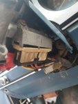
The write ups (which I've read many times) makes it seem so simple. Just rip out 95% of the wires and flip over the fender. Doesn't seem so simple though, when I go to do it. Lot's going on in there, and I don't want to remove something that will cause issues later...trying to go more scalpel than hatchet on this. Any help is appreciated. I understand on my non a/c truck, I need to find and preserve wires for choke, oil sender, engine temp sensor, alternator. But I'm sure other wires in that engine bay must also be left. FIRST...let me tell you I will be doing Duraspark version later after the core I have is rebuilt. In the meantime I'm putting in a points distributor from 74 Mustang II and non feedback carb. So I want to keep things in there I'll need for my 1984 truck DS conversion down the road. Going old school for now. I took some pictures of areas I hope to get some feedback on, and wrote my questions on each picture. I numbered them so you can reference appropriate image # in any replies. See images and provide any suggestions on what can go, and what to leave...and best practices there. Thanks in advance! ,
Picture #2 plug marked X. I found that one of the wires is a power when ignition on and one was the wire for the oil pressure sending unit. I would not cut that wire. Trace the wire from the oil pressure sending unit up to that plug. I used the power when ignition is on for the electric choke on the non-feed back carb.
 

Sponsored Ad


Sponsored Ad

TRS Events

Member & Vendor Upgrades

For a small yearly donation, you can support this forum and receive a 'Supporting Member' banner, or become a 'Supporting Vendor' and promote your products here. Click the banner to find out how.

Recently Featured

Want to see your truck here? Share your photos and details in the forum.

Ranger Adventure Video

TRS Merchandise

Follow TRS On Instagram

TRS Sponsors


Sponsored Ad


Sponsored Ad


Amazon Deals

Sponsored Ad

Back
Top