- Joined
- May 1, 2026
- Messages
- 12
- Points
- 101
- City
- Boston
- State - Country
- MA - USA
- Vehicle Year
- 1994
- Vehicle
- Ford Ranger
- Drive
- 2WD
- Engine
- 4.0L
- Transmission
- Manual
Hey Everyone,
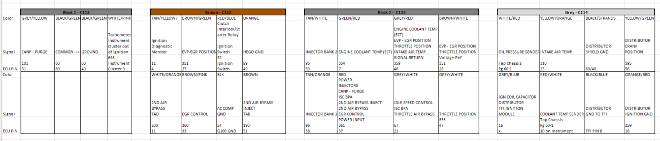
I am back with my continued wiring dilemma. Thank you for any insight in advance. I finished my harness pinout diagram.
So I ordered a new distributor, this came with a 7 pin connector instead of the 5 pin I expected.
Looking at this write up:
https://www.49ccscoot.com/manuals/FORD TFI electronic ignition.pdf
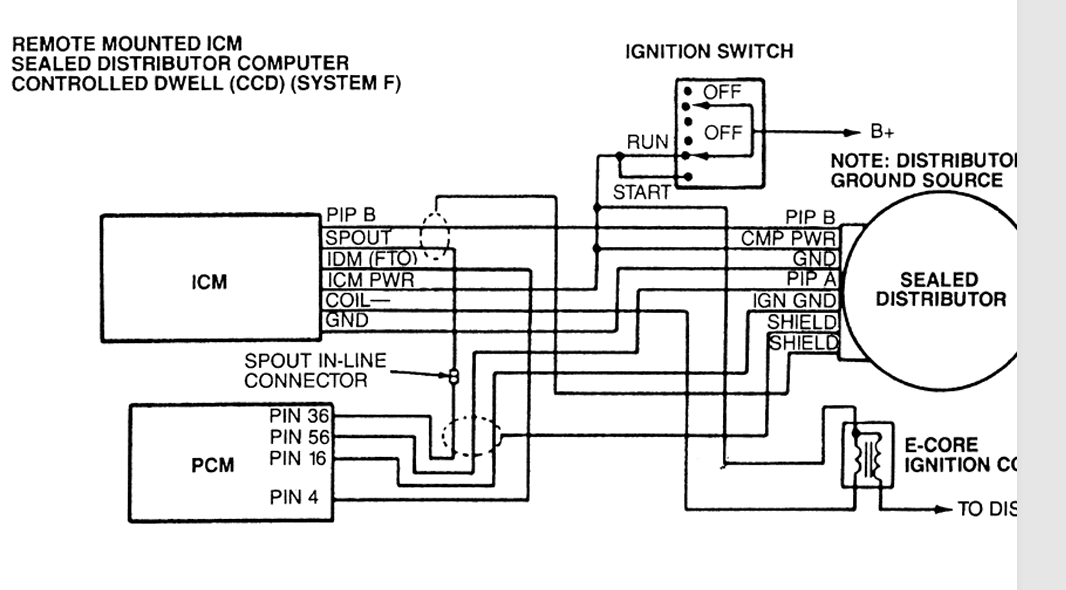
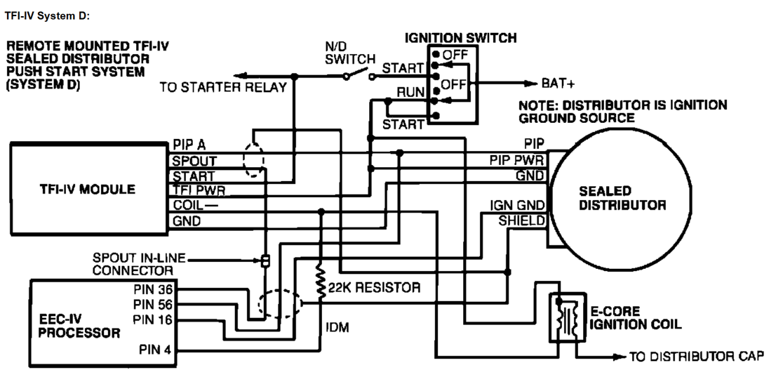
I can see a few differences in the circuit I expected. The first being: This above shows what I believe is a black remote mounted TFI module, and not a gray one. There's no 22 kohm resistor, and the TFI has a IDM connection and not start. That's fine. I have a gray TFI that I will use, so no worries there.
Below is the circuit I plan to reconstruct. My question now is this: What is the difference between PIP A and PIP B. Are these signals the same? I don't have an oscilloscope or picoscope or anything to check the signals besides a cheap amazon multimeter. I cant see any voltage coming the from the hall signals. My plan honestly was to pull PIP A from the 7 pin connector and send it into the gray TFI module and ECU. However, the diagram above specifies PIP B. Are these out of phase from each other at all? Which one is correct to send into the gray TFI? The rest of the pins are shield/ground differences, so I am not concerned there. But what is the difference between these PIP signals?
Beyond that, while researching I found this forum: https://www.ford-trucks.com/forums/1460766-distributor-signature-pip.html
I decided to check my own new distributor vein and found that I too have a thinner vein. However, mine has 8 veins and his has 6. Will I need a new one? What could be the purpose of this change? I wish I had kept the vein from the previous distributor but the whole thing was destroyed while removing it.
I am back with my continued wiring dilemma. Thank you for any insight in advance. I finished my harness pinout diagram.
So I ordered a new distributor, this came with a 7 pin connector instead of the 5 pin I expected.
Looking at this write up:
https://www.49ccscoot.com/manuals/FORD TFI electronic ignition.pdf
I can see a few differences in the circuit I expected. The first being: This above shows what I believe is a black remote mounted TFI module, and not a gray one. There's no 22 kohm resistor, and the TFI has a IDM connection and not start. That's fine. I have a gray TFI that I will use, so no worries there.
Below is the circuit I plan to reconstruct. My question now is this: What is the difference between PIP A and PIP B. Are these signals the same? I don't have an oscilloscope or picoscope or anything to check the signals besides a cheap amazon multimeter. I cant see any voltage coming the from the hall signals. My plan honestly was to pull PIP A from the 7 pin connector and send it into the gray TFI module and ECU. However, the diagram above specifies PIP B. Are these out of phase from each other at all? Which one is correct to send into the gray TFI? The rest of the pins are shield/ground differences, so I am not concerned there. But what is the difference between these PIP signals?
Function Diagrams — 1992 Ford F 150 2WD Pickup V8-302 5.0L Service Manual ~ LEMON Manuals
Repair manual for the 1992 Ford F 150 2WD Pickup V8-302 5.0L, including electrical diagrams, bolt torques, and labor times.
lemon-manuals.la
Beyond that, while researching I found this forum: https://www.ford-trucks.com/forums/1460766-distributor-signature-pip.html
I decided to check my own new distributor vein and found that I too have a thinner vein. However, mine has 8 veins and his has 6. Will I need a new one? What could be the purpose of this change? I wish I had kept the vein from the previous distributor but the whole thing was destroyed while removing it.