• Welcome Visitor! Please take a few seconds and Register for our forum. Even if you don't want to post, you can still 'Like' and react to posts.

Any engineers or engineering students here?


krugford

New Member
Joined
Aug 6, 2007
Messages
733
Reaction score
2
Points
0
Age
41
Location
Iowa
Vehicle Year
2003
Make / Model
Ford
Transmission
Automatic
I'll write up a summary of the thread, walk through the calcs for a given tube, and post it here. Probably be later this weekend. I'll try to make it with an Excel spreadsheet so you can modify numbers, etc. It'll also give some other people a chance to look through my numbers and make sure I've got it right too.

Probably be later this weekend.


Jim Oaks

Just some guy with a website
Administrator
Founder / Site Owner
Supporting Vendor
Article Contributor
TRS Banner 2010-2011
TRS Banner 2012-2015
TRS 20th Anniversary
VAGABOND
TRS Event Participant
GMRS Radio License
Joined
Aug 2, 2000
Messages
13,507
Reaction score
8,734
Points
113
Location
Nocona, Texas
Vehicle Year
1996 / 2021
Make / Model
Ford Ranger
Engine Type
4.0 V6
Engine Size
4.0 / 2.3 Ecoboost
Transmission
Automatic
2WD / 4WD
4WD
Total Lift
6-inches
Tire Size
33x12.50x15
I've got everything to date programmed in to Excel except this last formula using distances, weight, gravity, etc. It makes it easier to run calculations then writing everything out over and over. I was going to make it available for anyone else to use after I was done with it if they want to play around with material strengths.

I still have to figure out this last formula we were talking about. I haven't looked at it since I posted on 11/10. I think once I/we have a formula figured out for falling from a known distance and landing on a link centered on a rock I'll be content moving on to something other than tubing strength.

Just thought I'd give you a heads up. I don't want to put up something for download and have you feel like I stole your work. My basis for doing all this was not to create an Excel file for download, but decided I might as well share what I've done with others wanting to look at strengths of tubing.
 

krugford

New Member
Joined
Aug 6, 2007
Messages
733
Reaction score
2
Points
0
Age
41
Location
Iowa
Vehicle Year
2003
Make / Model
Ford
Transmission
Automatic
Not a problem. I haven't done anything in Excel yet. I am gonna do it as much for my own use as anything. This whole topic has got me thinking about doing my own four-link now....
 

Jim Oaks

Just some guy with a website
Administrator
Founder / Site Owner
Supporting Vendor
Article Contributor
TRS Banner 2010-2011
TRS Banner 2012-2015
TRS 20th Anniversary
VAGABOND
TRS Event Participant
GMRS Radio License
Joined
Aug 2, 2000
Messages
13,507
Reaction score
8,734
Points
113
Location
Nocona, Texas
Vehicle Year
1996 / 2021
Make / Model
Ford Ranger
Engine Type
4.0 V6
Engine Size
4.0 / 2.3 Ecoboost
Transmission
Automatic
2WD / 4WD
4WD
Total Lift
6-inches
Tire Size
33x12.50x15
Not a problem. I haven't done anything in Excel yet. I am gonna do it as much for my own use as anything. This whole topic has got me thinking about doing my own four-link now....
:headbang::icon_welder::headbang:
 

Jim Oaks

Just some guy with a website
Administrator
Founder / Site Owner
Supporting Vendor
Article Contributor
TRS Banner 2010-2011
TRS Banner 2012-2015
TRS 20th Anniversary
VAGABOND
TRS Event Participant
GMRS Radio License
Joined
Aug 2, 2000
Messages
13,507
Reaction score
8,734
Points
113
Location
Nocona, Texas
Vehicle Year
1996 / 2021
Make / Model
Ford Ranger
Engine Type
4.0 V6
Engine Size
4.0 / 2.3 Ecoboost
Transmission
Automatic
2WD / 4WD
4WD
Total Lift
6-inches
Tire Size
33x12.50x15
While the yield on a tube dropped from a known distance with a known weight may seem high, I'd still like to know how to calculate it.

What if the four link bars are 2.5" x 0.250" wall 4130 chromium-molybdenum tube, with tensile strength of 162 to 194 KSI and yield strength of 123 to 159 KSI? What if they were sleeved with another 2" x 0.250" wall 4130 tube or some other combination of larger 4130 with another 4130 sleeved inside it?
 

Jim Oaks

Just some guy with a website
Administrator
Founder / Site Owner
Supporting Vendor
Article Contributor
TRS Banner 2010-2011
TRS Banner 2012-2015
TRS 20th Anniversary
VAGABOND
TRS Event Participant
GMRS Radio License
Joined
Aug 2, 2000
Messages
13,507
Reaction score
8,734
Points
113
Location
Nocona, Texas
Vehicle Year
1996 / 2021
Make / Model
Ford Ranger
Engine Type
4.0 V6
Engine Size
4.0 / 2.3 Ecoboost
Transmission
Automatic
2WD / 4WD
4WD
Total Lift
6-inches
Tire Size
33x12.50x15
I haven't given up on this. I went back to the engineering book and took out these formulas for beams supported at both ends and struck in the center.

#1

P=[(Qal/4I)*(1+SQRT((96hEI)/(Qa^3)))]

#2

P=[(Wl/4Z)*(1+SQRT(1+2h)/(Wl^3)/(48EI)))]

#3

P=[(Wl/4Z)*(1+SQRT(1+(96hEI)/(Wl^3)))]

An approximate value for P is:

#4

P=a*((6QhE)/lI))

Where as:

P = Stress in PSI
a = Distance to extreme fiber from neutral axis
E = Modulus of elasticity (29,000,000)
h = Height dropped in inches
I = Moment of inertia
l = Length of beam in inches
Q & W = Weight dropped

Using a 2"x.375" wall (1.25"ID) tube with a weight of 1,250lbs and height of 36"

Results so far are:

#1 = 518,101psi
#2 = 583,506psi
#3 = 518,604psi
#4 = 495,512psi
 

krugford

New Member
Joined
Aug 6, 2007
Messages
733
Reaction score
2
Points
0
Age
41
Location
Iowa
Vehicle Year
2003
Make / Model
Ford
Transmission
Automatic
I'll have to look over those tomorrow. I believe those formulas are just combined and reduced from the general equations governing this drop. As your results show, they get similiar answers, but are off because they make different assumptions. Either that or there a unit conversion that's missing there. I'll post the results and formulas I used in my spreadsheet tomorrow to compare. I was getting around 2.4 million psi....

-krug
 

Jim Oaks

Just some guy with a website
Administrator
Founder / Site Owner
Supporting Vendor
Article Contributor
TRS Banner 2010-2011
TRS Banner 2012-2015
TRS 20th Anniversary
VAGABOND
TRS Event Participant
GMRS Radio License
Joined
Aug 2, 2000
Messages
13,507
Reaction score
8,734
Points
113
Location
Nocona, Texas
Vehicle Year
1996 / 2021
Make / Model
Ford Ranger
Engine Type
4.0 V6
Engine Size
4.0 / 2.3 Ecoboost
Transmission
Automatic
2WD / 4WD
4WD
Total Lift
6-inches
Tire Size
33x12.50x15
Ya, I'd like to see the formulas you came up with. You had PM'd me that you had came up with a 130,000psi result. I'd like to see that formula. That could work within the specs of some chromoly.
 

krugford

New Member
Joined
Aug 6, 2007
Messages
733
Reaction score
2
Points
0
Age
41
Location
Iowa
Vehicle Year
2003
Make / Model
Ford
Transmission
Automatic
Here's the calculations I used to come up with an estimate of the force required to stop a 1250lb weight, dropped from a height of 36 inches, in a distance that is less than the "maximum deflection before yield" of a tube that is 2.00" OD with a .375" Wall Thickness. (All units are/must be in inches, pounds, or seconds) (Force is applied perpendicular to tube at center of span)

Material Properties: (From www.matweb.com)
Material: 1020 Steel Cold Rolled
Yield Stress (Yield): 50,800 psi
Density: 0.284 lb/in^3 (pounds per cubic inch)
Elasticity Modulus: 29,700,000 psi

Geometry:
Tube OD (OD): 2.00 in
Wall Thickness: 0.375 in
Tube ID (ID): =OD-(2*Wall Thickness) = 1.25 in
Tube Length (L): 48 in

Section Properties:
Max Distance from Neutral Axis (c): =(OD/2) = 1 in
Cross-sectional area: =(pi/4)*(OD^2 - ID^2) = 1.91441 in^2
Second Moment (I): =(pi/64)*(OD^4 - ID^4) = 0.66556 in^4
Section Modulus (Z): = (I/c) = 0.66556 in^3
Force to reach yield stress (F1): =(4*Yield*Z)/L = 2817.52 lbf (pound-force)
Deflection at max stress (ymax): = ((F1)L^3)/(48*E*I) = 0.3284 in

Scenario Properties:
Height of Drop (h): 36 in
Gravity Constant (g): 386.088 in/s^2
Speed at Impact (V): =sqrt(2*g*h) = 166.728 in/s = 13.894 ft/s = 9.473 mph
Weight on corner of truck (lbm (pound-mass)): 1250 lbm
Acceleration (a): =(V^2)/2*ymax) = 42,323 in/s^2 = 2404 mph per second

Calculated Stresses
Force from Drop (F2): = (lbm*a)/g = 137,026 lbf (pound-force)

The reason for the gravitational correction factor in the force equation is because I am using the convention that on Earth, 1 lbf = 1 lbm. This means that a 1250 lbm weight will exert 1250 lbf on whatever it is sitting on. This convention means the standard Force equation (F = ma) is not valid without a correction factor for the gravitational constant. In this case 386.088 in/s^2. This is why I like the metric system. I may not be able to visualize what a Newton is, but I sure know what it does. :)

Bending Moment (M) (at center of beam): =(F*(L/2))/2 = 1,644,316 in*lbf
Bending Stress (sigma) (at tube surface): = (Mc)/I = 2,470,590 psi (lbf/in^2)

One thing that these equation DO NOT take into account is the actual energy that it takes to bend the link up to and even past yield stress. This would involve dynamic strain-rates and deformation energy. Neither of which I have enough experience in to perform rough calculations. For that, I would recommend a simple finite element analysis. I do currently have access to an FEA program that contains an explicit (capable of performing time-step calculations) solver at work. I am attempting to learn how to test a scenario like this one for my own personal curiosity. If I ever get my two parts to actually make contact instead of passing through each other, I'll let you know.

As a quick look, here's what the link would do with just the weight of the truck on it sitting still:

STATIC Load of Truck on Link:
Force on Link: 1250 lbf
Bending Moment = 15,000 in*lbf
Bending Stress = 22,538 psi
Factor of Safety = 2.254

This means you could STATICALLY apply a force of 2817.5 lbf to it before reaching yield stress. You'll also notice during the course of your calculations that the deflection required to reach yield stress is independent of wall thickness. This is because the maximum bending stress lies on the surface of the tube. Only the force required to reach this deflection changes with wall thickness.

Here's my spreadsheet if you want to play with it. It is "somewhat" user friendly....

View attachment Four Link Calcs(zipped).zip

Any questions? Just ask. I'm starting to have fun now.
 

Jim Oaks

Just some guy with a website
Administrator
Founder / Site Owner
Supporting Vendor
Article Contributor
TRS Banner 2010-2011
TRS Banner 2012-2015
TRS 20th Anniversary
VAGABOND
TRS Event Participant
GMRS Radio License
Joined
Aug 2, 2000
Messages
13,507
Reaction score
8,734
Points
113
Location
Nocona, Texas
Vehicle Year
1996 / 2021
Make / Model
Ford Ranger
Engine Type
4.0 V6
Engine Size
4.0 / 2.3 Ecoboost
Transmission
Automatic
2WD / 4WD
4WD
Total Lift
6-inches
Tire Size
33x12.50x15
Ok, so are you saying that 1,250lb corner of the rig is going to impact 2,470,590 psi of force on the link if dropped 36-inches?
 

krugford

New Member
Joined
Aug 6, 2007
Messages
733
Reaction score
2
Points
0
Age
41
Location
Iowa
Vehicle Year
2003
Make / Model
Ford
Transmission
Automatic
The force acting on the link is going to be 137,000 pounds for brief period of time. The stress in the link resulting from that force is going to be 2,470,590 psi. This far exceeds the yield strength of any material you are going to find. My calculation for the acceleration came from the assumption that the tube would not exceed yield stress. It does. Under this load, the link will deform and will not come back to it's original shape. In other words, it's gonna break.
 

Jim Oaks

Just some guy with a website
Administrator
Founder / Site Owner
Supporting Vendor
Article Contributor
TRS Banner 2010-2011
TRS Banner 2012-2015
TRS 20th Anniversary
VAGABOND
TRS Event Participant
GMRS Radio License
Joined
Aug 2, 2000
Messages
13,507
Reaction score
8,734
Points
113
Location
Nocona, Texas
Vehicle Year
1996 / 2021
Make / Model
Ford Ranger
Engine Type
4.0 V6
Engine Size
4.0 / 2.3 Ecoboost
Transmission
Automatic
2WD / 4WD
4WD
Total Lift
6-inches
Tire Size
33x12.50x15
OK, I'm ready to abandon the idea of calculating for a drop.

I think I'm going to design for 4x the force using the formula for force applied to the center of a link (Wl/4Z). I looked at 5x, but the link diameters seemed excessively huge.

The only other formula I'm still curious about was buckling. If you could reach the max 5500lb torque from a D60, how much force would it apply to the links? We discussed it some, but I don't think we ever came to a final decision on the proper formula to use and its application.
 

krugford

New Member
Joined
Aug 6, 2007
Messages
733
Reaction score
2
Points
0
Age
41
Location
Iowa
Vehicle Year
2003
Make / Model
Ford
Transmission
Automatic
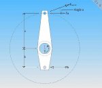
To find the force in the link due to axle torque, you need to know the torque output and the distance between the links.

simplebracket2.jpg

This is assuming a worst case scenario of having the tire trapped, or unable to turn, so that all of the torque goes into trying to spin the housing. It also assumes full throttle.... From the pic above:


Fa = T/(a+b)
Fb = T/(a+b)

Those equations above come from a simple supported beam (the bracket) with a moment load (axle torque) applied somewhere between the supports (the links)

Keep in mind that this assumes that the link is tangential to the torque moment. Since this is an off road truck, the axle is surely going to be below the frame mounts for the links. This means that for the same torque moment, the force on the link will change as the suspension cycles from droop to compression. If the link is at an angle away from tangential, then the force in the link will be the tangential force divided by the cosine of the angle. In the case of my drawing, the force on the upper link is:

Fupperlink = Fa/cos(Angle a)

The same procedure can be applied to the lower link.

Once you have the force, simple divide by the cross sectional area of the tube.

Calculations:

a = 8 inches
b = 2.5 inches
T = 5500 ft*lbs = 66,000 in*lbs
Angle a = 5 degrees
Tube OD = 2.00 inches
Tube ID = 1.25 inches
length = 48 inches
Elasticity Modulus: 29,700,000 psi
Cross-sectional area: =(pi/4)*(OD^2 - ID^2) = 1.91441 in^2
Second Moment (I): =(pi/64)*(OD^4 - ID^4) = 0.66556 in^4
k = sqrt(I/A) = 0.5896 in^2


Fupper = T/((a+b)*cos(a)) = 66,000/((8+2.5)*cos(5)) = 6309 lbf

Stress = F/area = 6309/1.914 = 3296 psi

Since the critical buckling load for this link is:

Fcr = (pi^2*E*A)/(l/k)^2 = (3.14159^2*29,700,000*1.914)/(48/0.5896)^2 = 84,676 lbf

This will give you a factor of safety for this load of around 25.7. Axle torque isn't going to buckle a link here.


If the links are parallel, then they will have equal and opposite forces applied to them. If they are not parallel, then the forces will not be the same because of the different angles between the link and tangential.

If the brackets are going to sweep forward slightly, this will increase the forces in the links and decrease the bending forces on the actual bracket itself because of the associated increase of <Angle a> in the image above.
 

Sponsored Ad


Sponsored Ad

Member & Vendor Upgrades

For a small yearly donation, you can support this forum and receive a 'Supporting Member' banner, or become a 'Supporting Vendor' and promote your products here. Click the banner to find out how.

Latest posts

Truck of The Month


Shran
April Truck of The Month

Recently Featured

Want to see your truck here? Share your photos and details in the forum.

Follow TRS On Instagram

TRS Events

25th Anniversary Sponsors

Check Out The TRS Store


Sponsored Ad


Sponsored Ad

Sponsored Ad


Amazon Deals

Top