
Lock-Right Lockers for the Ford Ranger / Bronco II
LOCK-RIGHT lockers are designed for use in ‘open’ differentials and WILL NOT work in Limited Slip differentials. Here are the Lock Right part numbers for use in your Ford Ranger or Bronco II.
- Ford 7.5-Inch Axle: 1830-LR
- Ford 8.8-Inch Axle 28-Spline: 1820-LR
- Ford 8.8-Inch Axle 31-Spline: 1822-LR
- Dana 35 TTB (ABS): 2311-LR
- Dana 35 TTB (Non-ABS): 2310-LR
Lockers In A 1998-2011 Ford Ranger
From 1998-2000 the Ford Ranger 4×4 used PVH locking hubs. From 2001-2001 it used a live axle which means that the axle was aways spinning. In a live axle, the locker will try to force both front wheels to turn at the same speed. During a turn on dry pavement (where there is a large difference in the distance the inner and outer wheels travel), this resistance will fight your steering input, potentially causing the truck to push or understeer.
The 2311-LR states that it will fit the 1998-2011 Ford Ranger 4×4, but it is not recommended for the 2001-2011 Ford Ranger except for off-road use.
Background Information
The differential case is the round housing inside the rear axle assembly to which the ring gear is bolted, and which contains the differential spider and side gear assembly. It is installed in the differential carrier, which is the housing that holds the case, drive pinion gear, bearings, etc.
The carrier may be removable (as part of a “drop-out” unit, or third member), or it may be integral (as a permanent part of the axle assembly, mounted in the vehicle). This manual covers the integral carrier design, both C-clip and non-C-clip versions.
The LOCK-RIGHT is designed to fit into standard open differential cases only, not into limited-slip (clutch-pack) type cases. If your vehicle contains a limited-slip
unit you will need to purchase a standard open differential case, thrust washers and pinion shaft before proceeding.
A word about axle shaft thrust blocks: A few differentials, such as the Jeep® AMC-20 and the older 19-tooth Spicer® 44 axle, use a thrust block between the inside ends of the axle shafts as a part of the end play adjustment. When installing a LOCK-RIGHT, this block is re-used along with the original axles so that the original end play adjustment does not change. However, if the original axles are changed to different original-type axles, the block will continue to be used but the end play must be re-adjusted (see your vehicle’ s shop manual for the procedure). If the axle is changed to another type that does not need end-play adjustment, such as a one piece design, the thrust block may be omitted. (In the Land Cruiser, the block is never used.)
A word about side gear thrust washers: All differentials originally had a thrust washer under each side gear. Thrust washers are large in diameter and between
about 1/32-inch (.031, or 0,76-mm) and 1/16-inch (.062, or 1,52-mm) thick. If either one or both are missing from the original differential, obtain new one(s) before proceeding!
The LOCK-RIGHT is designed to be used with a correct thrust washer under each coupler, and failure to use a thrust washer is easy to observe during inspection and will void the warranty. Please see pg. 3 for important information regarding the thrust washers and proper spacing between the LOCK-RIGHT couplers/spacers and the Pinion shaft before proceeding with the installation.
A word about C-clips: Many integral carrier differentials have the axle shafts retained by C-clips. These are semi-circular pieces of hardened steel, similar to a
washer with one side cut out, that fit into a groove in the end of the axle shaft and into a pocket in the side gear. The axle shaft is held in place by the pinion (spider gear) shaft. The LOCK-RIGHT is designed for many of these axles, and their installation is covered in this manual. This type of axle is the easiest in which to install a LOCK RIGHT, typically requiring about one hour for the procedure.
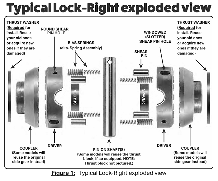
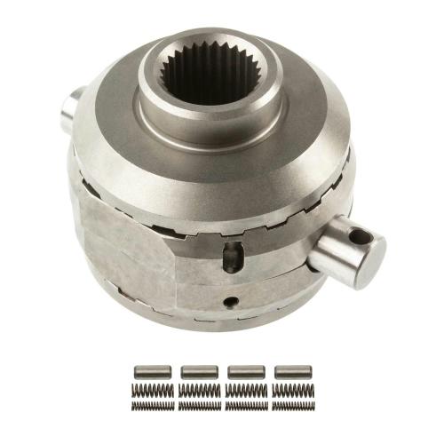
NOTE: The LOCK-RIGHT shown in the various figures is of a typical unit and may not exactly depict your particular model. See (Figure 1) on page 5 for an exploded view of a typical LOCK-RIGHT.
Preliminary Steps
The following steps are only a general guide to preliminary operations used for preparing your vehicle for LOCK-RIGHT installation. For detailed information, refer to your shop manual. In general, the preliminary steps include:
a) Blocking the vehicle, putting transmission in neutral;
b) Loosening the wheel lug nuts (optional with C-clips and other axles);
c) Jacking up the axle; securely resting it on jack stands;
d) Removing the tires;
e) Disconnecting the brake lines and emergency brake cables;
f) Pulling out one or both axles a few inches.
Determination of Axle Type
1. Remove the differential cover and drain the oil.
2. Inspect to determine axle assembly type. If it is a C-clip design, proceed directly to SECTION 2. If not, continue with step 3.
3. Determine if the ring gear is thin enough to be able to pull the pinion (spider gear) shaft out past the teeth. If so, proceed directly to SECTION 2. If not, continue to SECTION 1.
SECTION 1:
Removal of the Differential Case and Ring Gear Assembly From the Vehicle (Thick ring gear)
1. Perform the operations listed below and as described in your shop manual that apply to your vehicle. The axle shafts should be pulled out about six inches for differential case removal.
2. Using a center punch, mark both the carrier and bearing cap on the ring gear side with one punch mark each and on the other side with two marks. The caps
are not interchangeable, because each one is line-bored with the carrier. These marks are very important to correct re-assembly!
3. Rock the ring gear back and forth to get a “feel” for the amount of backlash present. This amount of rotation will be rechecked when the differential case is
installed to determine if it has been done correctly.
4. Remove the bearing caps and then the differential case and shims from the carrier as described in the shop manual (some axle designs may require the use
of a carrier spreader tool). Be sure to put a small grind mark on each shim or tag them so that they can be replaced on the same side.
5. Remove the differential bearing race from the side with one punch mark first. Put a very small grind mark on the out side of it, or use a tag. Be sure that you
can identify it for proper re-assembly on the same side.
6. Remove the other bearing race.
7. Remove the ring gear from the case. It may need to be tapped off with a brass mallet (see the shop manual). Mark it so that it can be re-installed in the same rotational orientation as when removed.
8. Proceed from SECTION 2, “Parts Inspection”.
SECTION 2:
Disassembly of the Differential Case With Thin Ring gear, and C-clips (in the vehicle); also with thick ring gear (after case is removed from vehicle)
NOTE: If the axle assembly is a C-clip design or has a thin ring gear, the differential case remains in the vehicle and the ring gear side axle shaft does not need to be disturbed—it simply remains bolted in place and the LOCK-RIGHT installation is done by only partially removing the opposite axle shaft.
1. Remove the pinion shaft retaining pin, using a long punch. In the vehicle, the left bearing cap may need to be removed; for C-clip differentials only, unscrew the pinion shaft bolt.
2. Remove the pinion shaft.
3. For C-clip differentials only: The C-clips are located in a groove in the end of each axle shaft and are held in a pocket in the side gear by the pinion shaft. “Bump” each tire inward slightly to free the clips; they will fall out to free up the internal parts.
4. For installations with the differential case in the vehicle, leave the ring gear side axle bolted in place; pull out only the other axle shaft about two inches.
5. Remove the spider gears, side gears, all washers, and axle shaft thrust block (if used in your assembly).
Parts Inspection
NOTE: The LOCK-RIGHT utilizes your differential case, side gear thrust washers and pinion shaft (plus the axle shaft thrust block, if used), and they must be in excellent condition. The spider gears and washers are not used. If the following inspection shows that anything is bad, buy new parts from your dealer!
1. Thoroughly clean the differential case and wash remaining parts with solvent, then dry them.
2. Inspect the pinion shaft. Any noticeable grooves or galling may weaken it and can also adversely affect the operation of your new LOCK-RIGHT. If it is not in excellent condition, obtain a new one.
3. Inspect the side gear thrust washers. They are important to the correct positioning of the LOCK-RIGHT parts. If they are excessively worn or are cracked, obtain new ones. If several thicknesses are offered, try to obtain the same size as the old ones. NOTE: There should be TWO thrust washers of about equal thickness, one under each side gear. See pg. 3 for important additional information regarding the thrust washers & proper spacing in relation to the pinion shaft.
4. Inspect the thrust block (if used). Be sure that the ends are smooth and not galled.
5. Inspect the case for any chips, cracks or similar damage. Also inspect the bearings, if the case is out of the vehicle. If the case or bearings look bad, replace them. However, if you do, remember that the old shims will no longer be correct; the ring and pinion backlash and bearings preload will need to be reset with a dial indicator as described in the shop manual.
LOCK-RIGHT installation: Preparing The Parts For Assembly
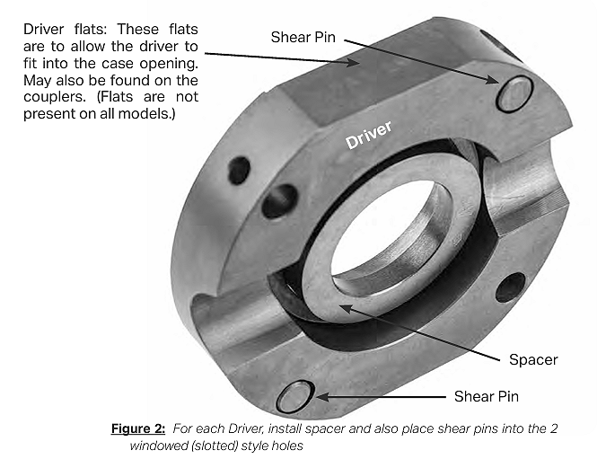
1. Coat the teeth of the couplers and drivers, the large center holes of the drivers, and both sides of the thrust washers with medium grease. Also place a little grease in each of the two windowed holes in each driver. The grease will help hold things in place and assist with functioning until the gear oil circulates.
NOTE: For clarity, the images that follow feature assembly without using grease.
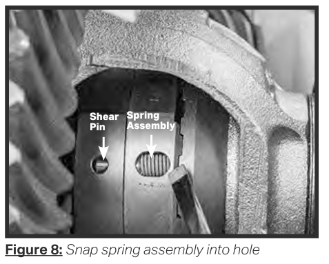
2. Place a shear pin into each windowed (slotted) hole. It should be about flush. (Figure 2).
3. Place a spacer into the center of each driver, wide end toward the teeth if not symmetrical. (Figure 2).
4. Press a thrust washer (with grease added) onto the back of each coupler.
5. Insert a small spring into each of the larger springs and add a little grease to the coils to hold them together. Set them aside
SECTION 3:
Assembly of the LOCK-RIGHT Parts Into the Differential Case
1. Install a coupler and thrust washer assembly in the ring gear end of the differential case and over the axle splines, if in the vehicle. Note that the couplers in
some models may have flats for clearance. If an axle shaft thrust block is used, place it in the center of the second coupler now if the installation is being
done in the vehicle. If not, it may be installed later.
2. Place the second coupler and thrust washer assembly into the other end of the differential case (Figure 3).
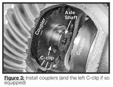
3. For C-clip differentials only: Place a C-clip with the ends pointing down into the ring gear side axle shaft end groove and pull the tire out sharply to seat the
clip (Figure 3). Then, carefully push the other axle into the second coupler splines until the end of the axle shaft is even with the coupler surface. Keep the
coupler seated in the case. IMPORTANT! Be sure to have the spacers correctly placed in the drivers before doing the following steps!
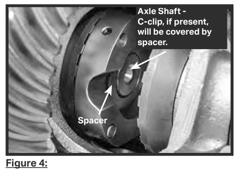
4. Pick up one of the driver-and-spacer assemblies. Orient its teeth toward the ring gear flange and hold it so that the flats (if present) will clear the sides of the case. Place it on the teeth of the coupler and press it into the grease (Figure 4). Reach into the center and push the spacer down onto the coupler shoulder (and over the C-clip, if so equipped).
5. For NON-C-clip axles only, repeat step 4 for the other driver & spacer assembly, then proceed to “Differential case assembly completion (All models)” on pg. 22. For C-clip axles only, follow the steps below to install the second C-clip and other driver:
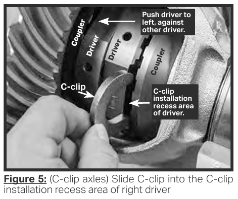
a) Place the other driver assembly in the differential case. Push it to the left, touching the other driver (Figure 5).
b) If necessary, use a thin standard screwdriver between the driver & coupler teeth to push its spacer leftward and back into the center of the driver.
c) Rotate both drivers with the left tire until the C-clip installation recess area of the right driver is facing you.
d) Tap the right tire inward to line up the C-clip slot at the end of the axle shaft with the gap between the driver and coupler. Make sure to keep the right coupler
fully seated in the case so it doesn’t get in the way and close the gap.
e) Slide the C-clip through the recess in the driver’s teeth and into the C-clip groove at the end of the axle shaft (Figure 5). If needed, use a thin screwdriver to help push the C-clip all the way in.
f) Once in, pull the right tire out sharply to seat the C-clip.
g) Rotate the right tire 1/4-turn so that the C-clip ends are pointing downward. This will help prevent it from falling off.
h) Rotate the left tire to position both drivers so that the semi-circular pinion shaft recess in the right driver is facing out.
i) Push the right driver to the right and into the grease in the coupler teeth.
j) Through the pinion shaft recess, push the right spacer to the right, over the C-clip and axle shaft end.
Differential Case Assembly Completion (All models)
NOTE: These steps are for the differential case that has been removed from the vehicle and is on the bench, as well as for those remaining in the vehicle.
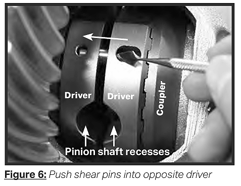
1. Rotate the right driver until one of its long window holes (containing a shear pin) faces you and rotate the other driver until one of its empty round shear pin holes lines up with the window hole.
2. Push the shear pin out of the window hole and into the pin hole in the opposite driver with a small, pointed tool (Figure 6).
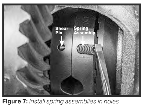
3. Place one end of a spring assembly (small spring inside the large one) into the windowed hole, behind the shear pin (Figure 7). Compress it with a small screwdriver and pop the bottom into the window hole (Figure 8). Push on the bottom coils to be sure that the spring snaps in and is seated all the way. Rotate the drivers and do the same procedure for each of the other three shear pins and springs.
4. Reach into the driver’s pinion shaft recess with your finger and be sure that the spacers are pushed fully outward onto the couplers.
5. Rotate the drivers so that the large recesses line up with the pinion shaft holes in the differential case.
6. If an axle shaft thrust block is being used, push it into the center of the assembly and line up the large hole with the pinion shaft holes. If in the vehicle, push
the right axle shaft inward now, into the coupler splines, to move the block to the center.
7. Carefully insert the pinion shaft into the hole and guide it through the drivers, past the spacers (and through the thrust block, if used). It should insert easily by
hand. If not, tap it in, being very careful not to get the inner end caught on something. Be sure to orient it so that its retaining pin hole will line up with the hole in the differential case (Figure 9).
If the pinion shaft will not insert, or is hard to insert, be sure that the correct thrust washers are being used and that the spacers are oriented with the widest side (opening) fitting down over the coupler shoulder. Rotate the drivers and couplers back and forth to be sure that they are not binding.
8. Install the pinion shaft retaining pin. If the pin is solid, as opposed to a roll pin, slightly deform the metal on the side of the hole to help hold it in place (see the
shop manual). For C-clip Axles only: Screw in and tighten the bolt.
9. For differential cases out of the vehicle: The case should still be on the bench after the preceding steps install the ring gear now and torque the bolts. Continue to next step.
Assembly of Differential Case Into Vehicle
(Thick ring gear; differential case was removed from vehicle)
1. Clean the axle housing interior, cover, mounting surface and drain plug.
2. Place the correct bearing races onto each end of the differential case, ready to install.
3. If shims are used, locate them near the correct ends of the case, ready to install.
4. Install the differential case in the carrier as described in the shop manual. Generally, this will involve placing the differential case and correctly-located bearing
races with one shim into the carrier and then tapping in the shim on the other side or pressing the case in if the shims are already mounted under the bearings. In some designs a spreader for the housing may be required.
5. Replace the bearing caps in their marked positions and torque the bolts to their correct value. Consult the shop manual for the exact procedure.
6. Finish the installation of any remaining parts by reversing the order of disassembly—in general, the axles/backing plates, brake lines, emergency brake cables, and tires. If your vehicle uses an axle shaft thrust block, be sure that the correct axle shims are in place at the outer ends of the axle shafts. In these designs there should be little or no end play. Also note that in some designs the last 1/8” or so of the backing plate installation may be a light press fit and the axle shaft may appear to be hitting something; tap the outside end of the axle shaft and it should go in.
Assembly Inspection
Inspect your work. Look for anything that is not correct. Be sure that the drivers rotate back and forth smoothly, stopping at the pinion shaft. Use a light to see that the spacers (and thrust block, if used) are in place and that the springs are working properly. When the above installation steps are completed, all the parts should be in exactly the same positions as they were when the installation began. If the differential case has been removed from the vehicle, the backlash and preload settings should be unchanged from before and no further adjustments will be needed. To be certain, rock the ring gear back and forth to see if the backlash appears to be the same as it was prior to the installation. If not, it will need to be reset with a dial indicator as described in the shop manual. Rotate the ring gear one revolution to be sure that nothing is binding.
Your LOCK-RIGHT installation should now be complete. As a preliminary test only, prior to the final test on the next page, rotate the tires back and forth (transmission out of gear and drive shaft free).
The drivers should randomly unlock and “click” as the tires move. Note that the tires will NOT lock together.
This easy-unlocking characteristic is a unique feature of the LOCK-RIGHT and is perfectly normal. Watch to be sure that both sets of teeth engage and disengage. If they do, your installation has probably been done correctly and your LOCK-RIGHT is ready for its final test, described in Section 5 on page 32.
Note that the clicking sound is much louder now than what you will hear during driving because the cover is off and no oil is present. As an additional check to be sure that everything has been installed correctly, use a small ruler, vernier caliper or blade-type feeler gauge. The distance between the halves of the LOCK-RIGHT, that is, between the two drivers, should be about 5/32” (.152”, or 3.86mm). The tolerance limits are between .145” (3.68mm) and .170” (4.32mm). If this distance is much over .170”, either the case is quite worn, or the thrust washers are missing or are too thin and the problem should be corrected before proceeding further.
SECTION 4:
Vehicle Final Assembly When everything is correct, clean the axle housing gasket surface and install the cover using a gasket and/or sealant as appropriate, and torque the bolts. Add the proper amount of gear oil.
Note that we suggest using medium-to-heavy oils as recommended by the manufacturer, unless the vehicle will be used in very cold weather. Thicker oil, such
as 85-140, reduces the “clicking” noise sometimes heard during tight turns and provides adequate lubrication when the assembly becomes hot. Also see the section in the Vehicle Operator’s Manual regarding temperature.
Tire Diameters
To help assure a long life for your new LOCK-RIGHT, tire diameters should be as nearly equal as possible. DO NOT change the inflation pressure to vary the
rolling radius of the tire! This practice can be dangerous if one of the tires is under-inflated, resulting in excess heat, faster tire wear and more difficult vehicle control.
The best way to equalize the rotation is to measure the circumference of all the tires, including the spare. Choose ones that are within about 3/8” or less of each other (do not change from side-to-side if they are radials). If one tire is much more worn than the other one, they both should be replaced for safety reasons
SECTION 5:
Testing Your Installation
1. Be sure that the vehicle is safely blocked. Leave the axle assembly on the jack stands, with both tires free to rotate and the emergency brake off.
2. Put the transmission and transfer case in gear to lock the drive shaft.
3. Rotate one of the tires in the forward direction with your hand until it stops, then hold it. That side of the LOCK-RIGHT is now locked.
4. Rotate the other tire in the opposite (reverse) direction. The LOCK-RIGHT should “click” as the coupler attached to the axle rotates.
5. Rotate the first tire in the reverse direction and hold it; repeat step 3, rotating the other tire in the forward direction.
6. Repeat steps 2-4, rotating and holding the second tire to lock the second side.
SECTION 6:
Driving Your Vehicle
If the foregoing measurements and tests have been successfully completed, apply the emergency brake and remove the vehicle from the jack stands. Your vehicle should now be ready to drive.
Carefully read and understand the driving information contained in the LOCK-RIGHT Vehicle Owner’s Manual! Safe and effective use of your new LOCK-RIGHT
equipped vehicle depends on knowledgeable operation, and this can only be done by understanding its characteristics before you start.
SECTION 7:
Subsequent Disassembly
If something is not correct now or if you need to disassemble your LOCK RIGHT in the future, we will briefly describe the procedure here. We will assume that
the case has a thin ring gear and remains in the vehicle, or that it has a thick ring gear and has been removed from the vehicle and is on the bench.
NON-C-Clip Axles
1. If the case will remain in the vehicle (thin ring gear), pull out only the right axle shaft about two inches. Otherwise, remove the differential case from the vehicle and place it in the bench.
2. Remove the pinion shaft retaining pin and the pinion shaft.
3. Rotate the drivers until one of the right window holes faces out. Push under the spring with a small sharp-pointed pick and pry the end up. Push a small screwdriver or bent piece of small wire (a paper clip works well) under the spring and pop the bottom out. Push the shear pin out of the pin hole and into the window hole. Repeat for the other three springs and pins.
4. Position the case horizontally and push in the spacers so that they are in the middle of the drivers. If a thrust block is used, push it into the right coupler splines.
5. Remove the driver and spacer opposite the ring gear flange first and then remove the second driver.
6. Remove the couplers.
C-Clip Axles
1. Remove the pinion shaft retaining bolt and the pinion shaft.
2. Rotate the drivers until one of the right window holes faces out. Push under the spring with a small sharp-pointed pick and pry the end up. Push a small screwdriver or bent piece of small wire (a paper clip works well) under the spring and pop the bottom out. Push the pin out of the pin hole and into the window hole. Repeat for the other three springs and pins.
3. Move the right driver to the left, touching the left driver.
4. Move the right spacer to the left, into the center of the left driver with a thin standard screwdriver or similar item.
5. Rotate the left tire and both drivers until the C-clip installation recess in the teeth of the right driver is pointing down.
6. Tap the right tire inward to release the C-clip so that it falls down, through the recess.
7. Rotate the left tire to rotate both drivers and allow the C-clip to drop out of the case.
8. Pull the right tire out about one inch.
9. Push the spacers into the centers of the drivers.
10. Remove the driver and spacer opposite the ring gear flange first and then remove the second driver.
11. Remove the left C-clip.
12. Remove the couplers.
– END
Manual Addendum 1830 Installation #1000-762
Background
The Ford 7.5-inch differential is unique in C-Clip designs because the pinion shaft cannot be removed when a low gear ratio (high numerical ratio) is installed – the ring gear is too thick. To solve this problem, Ford cuts away a portion of the original pinion shaft for over half its length, which will not allow it to be used with your new LOCK-RIGHT.
LOCK-RIGHT Engineering has developed a pinion shaft that will allow the pinion shaft to remain in the differential case yet will enable the locker to be installed. The following procedure describes this special installation, for thick ring gears only. If the pinion shaft can be removed while the differential case is in the vehicle, install the LOCK-RIGHT as shown in the enclosed manual.
Disassembly
1. Remove inspection cover.
2. Slide the pinion shaft over the teeth.
3. Remove the C-Clips.
4. IMPORTANT! remove and discard the O-Ring, if present, from the C-Clip groove in each axle shaft!!
5. Pull both axle shafts out six inches.
6. Use a center punch to mark the bearing cap and carrier on the ring gear side with one mark and on the other side with two marks.
7. Remove the bearing caps.
8. Remove the differential case along with the bearing races and shims.
9. Put a single small grind mark on the outside of the bearing race and the shim that are on the side with one punch mark so that they can be placed back on the same side during assembly.
10. Remove the ring gear from the differential case.
11. Remove the differential case internal parts.
Assembly of the LOCK-RIGHT into the Differential Case
1. Put grease on the thrust washers and couplers.
2. Place a pin into each of the deep (window) holes in the drivers.
3. Place a spacer into the center of each driver.
4. Place the couplers and thrust washers into the differential case.
5. Place the drivers into the differential case, onto the coupler teeth.
6. Install the new pinion shaft and also loosely install the pinion shaft retaining bolt. It will be removed again later.
7. Install the ring gear.
Assembly of the Differential Case into the Vehicle
1. Place the bearing race with the mark on it on the proper end of the differential case. Place the other race on the other end of the case.
2. Install the differential case and shims into the vehicle (be sure to place the marked shim on the proper side).
3. Install the correctly marked bearing caps on each side.
4.Torque the bearing cap bolts.
5. Remove the shaft retaining bolt.
6. Push the pinion shaft outward toward the retaining bolt side by about 3/16-inch. NOTE: A slot is located on one side of the pinion shaft near the end by the hole. This slot corresponds to the side on which the grooves are located and can be used to turn the shaft with a screwdriver.
7. On the side of the assembly where the slot on the shaft end points, separate the driver and coupler teeth. Reach in through the cutout in the driver teeth with a small pick or awl and push the spacer into the curved grooves in the pinion shaft. This positioning of the spacer allows insertion of the C-Clip.
8. Push the axle shaft into the coupler until the C-Clip groove is accessible.
9. Insert the C-Clip through the cutout in the driver and into the groove in the axle shaft. NOTE: If replacing a limited slip differential, be sure to obtain two original Ford C-Clips. Some aftermarket clips are dished and will not function properly.
10. pull the tire out to seat the clip.
11. Using a screwdriver in the slot, rotate the pinion shaft 180 degrees. This movement pushes the spacer down over the first C-Clip and re-locates the grooves in the shaft over the second spacer.
12. Repeat steps 8 – 11 for the second C-Clip.
13. Push the shaft back into the case so that it is ready for the retaining bolt. The grooves in the shaft move inward so that the spacer is now locked in place.
14. Install the pinion shaft retaining bolt.
15. Perform the tire rotation test as described in the installation manual.
16. Replace the cover and add oil.
17. Be sure to read and understand the driving instructions in the LOCK-RIGHT Owner’s Manual.
18. Climb!
Lock Right Parts

Lock-Right Website
PowerTrax – Extreme Traction Systems – Lockers, Limited Slip and Posi Differentials
Related Articles
Installing A Lock-Right Front Locker
Picking A Differential For Your Ford Ranger
Locker Comparisons – Understanding Differentials/Lockers
Gears and Lockers Installation
Cross Pin Clearance – Grinding Gear Teeth
Ford Ranger 4×4 Front Axles 1983-1997
1983-2011 Ford Ranger Off-Road Builders Guide
Last Updated:
About The Author
Jim Oaks is the founder of TheRangerStation.com, the longest-running Ford Ranger resource online since 1999. With over 25 years of hands-on experience building and modifying Ford Rangers — including magazine-featured builds like Project Transformer — Jim has become one of the most trusted authorities in the Ford Ranger off-road and enthusiast space.
Since launching TheRangerStation.com, Jim has documented thousands of real-world Ranger builds, technical repairs, drivetrain swaps, suspension modifications, and off-road adventures contributed by owners worldwide. TheRangerStation.com has been referenced in print, video and online by enthusiasts, mechanics, and off-road builders looking for practical, and experience-based information.