
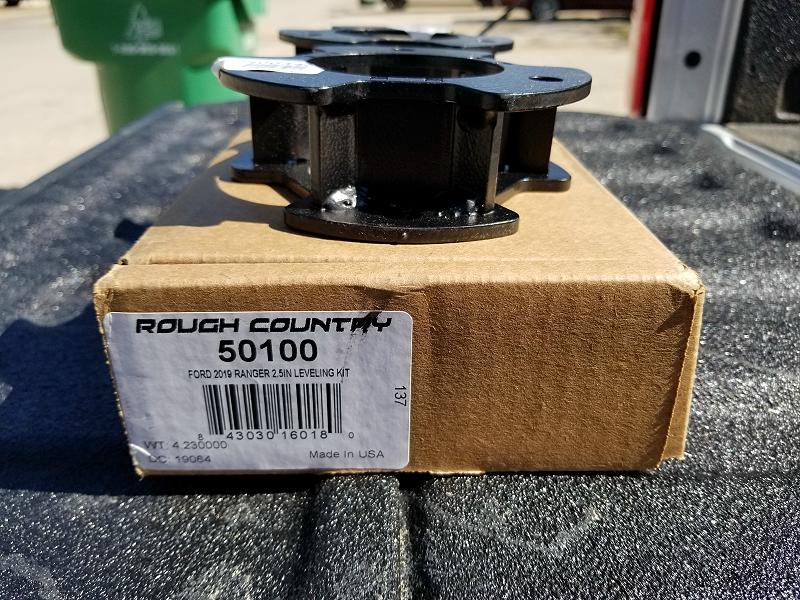
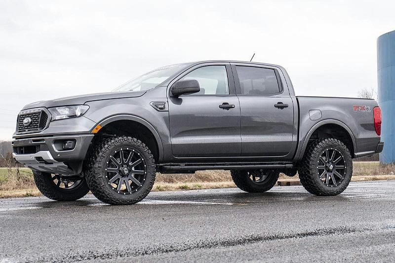
Note: Rough Country gave me this 2.5-Inch Leveling Kit to use on the 2019 Ford ‘Loan Ranger’. Although I went through the steps to install the leveling kit, I didn’t leave it installed. I didn’t want to go through the process of removing the kit before I gave the Ranger back to Ford, and I wanted to see how capable the truck would be on my adventures with a truly stock suspension. When the ‘Loan Ranger’ was given back to Ford, the leveling kit was given to ‘Broncojumper87’ and he is now using it on his Ranger.
Tools Needed:
- 8mm Wrench and Socket
- 10mm socket
- 15mm Socket
- 18mm wrench and socket
- 19mm Socket
- 3/4 Wrench
- Ratchet
- Hammer
- Wheel chocks
Kit Contents:
- 2-Front Strut Extensions
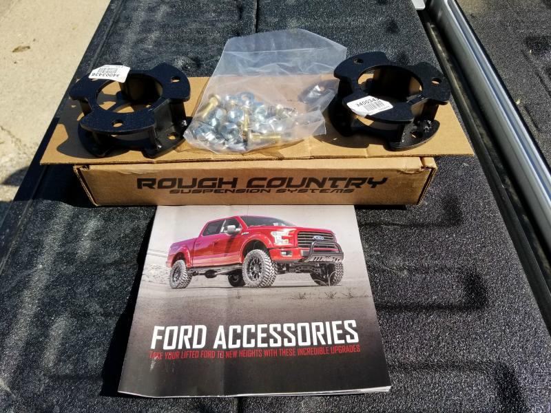
Hardware Included:
- 10mm stud bag
- (6) 10mm Studs
- (6) 10mm Lock Washers
- (6) 10mm Flat Washers
- (7) 10mm Nuts
- (1) 1/2”Jam Nut
Installation Instructions:
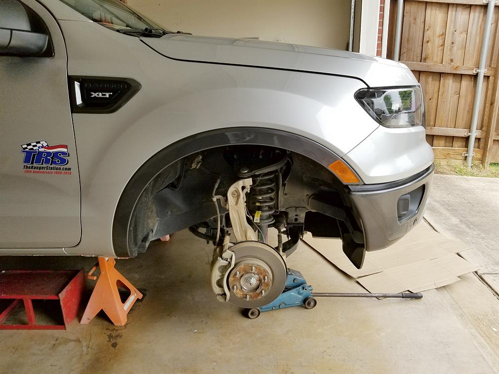
1. Chock the rear wheels and jack up the front of the vehicle.
2. Place jack stands under the frame rails and lower onto jack stands.
3. Remove the wheels/tires using a 19mm socket.
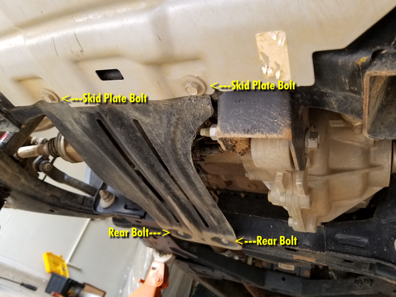
4. Loosen the front (2) skid plate bolts, remove the rear (2) bolts this will allow you to slide the skid plate back and remove, use a 15mm socket. set aside the bolts and skid plate for reuse.
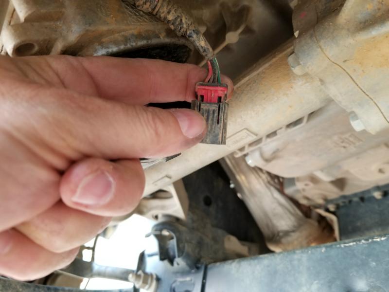
5. Remove the (3) EPAS (Electronic Power Assist Steering) Plugs as shown located on the steering assembly by the front differential. This must be done BEFORE installation is started.
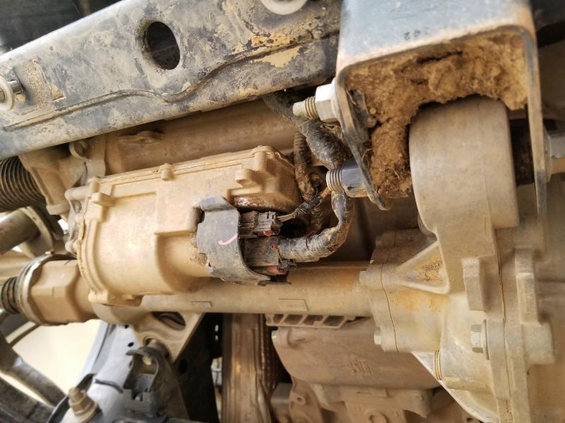
These plugs have a red lock tab that needs to be pulled outward before you can pull the plug off. Be very careful not to break it since it’s plastic.
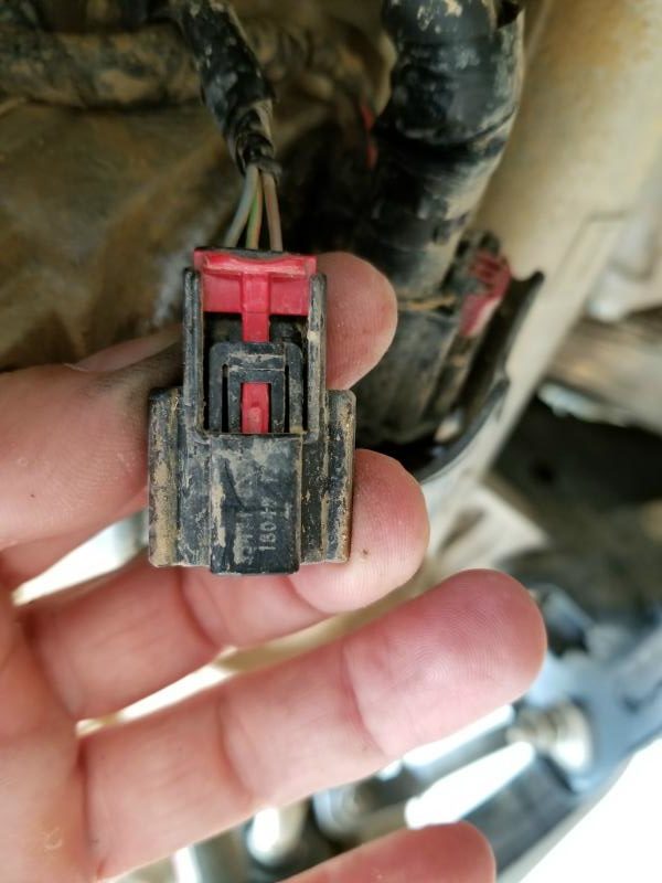
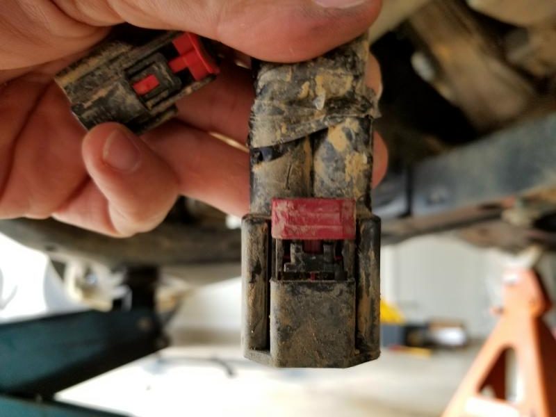
Here’s what each of the plugs look like so you can see what you’re working with:
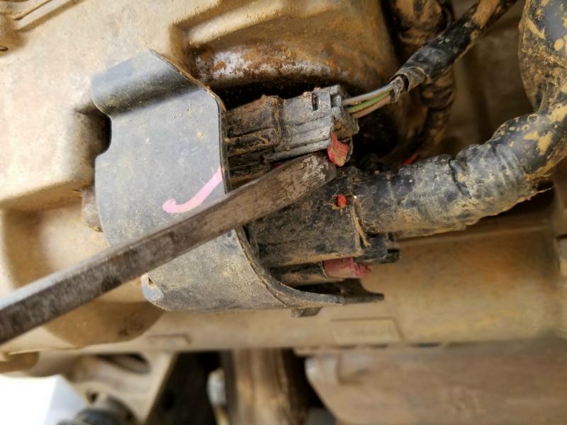
Notice how the plug above has a black tab that you pull down when the red tab is pulled back?
None of these plugs can be squeezed to release the connection until the red tabs are pulled back to unlock the plug.
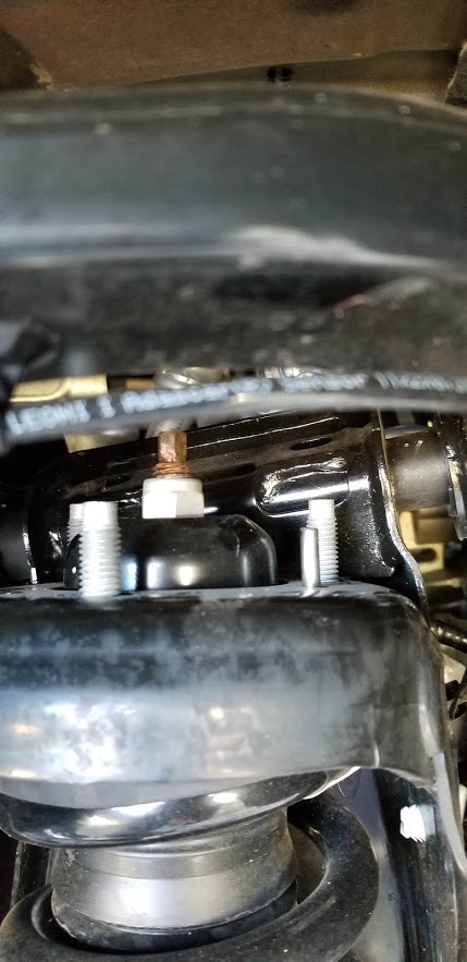
6. Disconnect the sway bar link from the knuckle, use an 18mm to remove the nut. Retain hardware for reuse.
The stud in the sway bar was turning with the wrench, so I stuck an Allen wrench in it to hold it in place. I’m sorry, I forgot to note what size Allen wrench it took. The ‘Tools Needed’ in the instruction sheet never mentioned an Allen wrench.
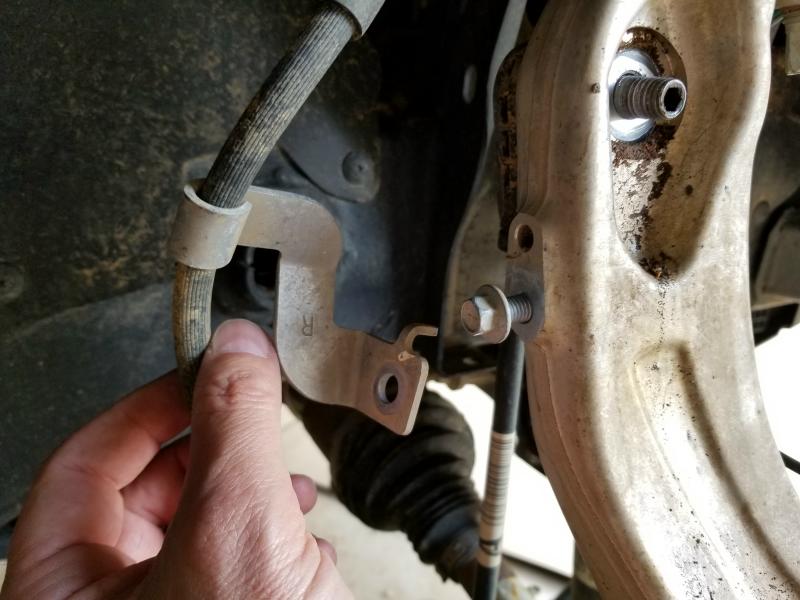
7. Remove the ABS wire bracket from the front side of the knuckle, use an 8mm socket, remove the brake line bracket from the back side of the knuckle, use a 10mm socket. Retain hardware for reuse.
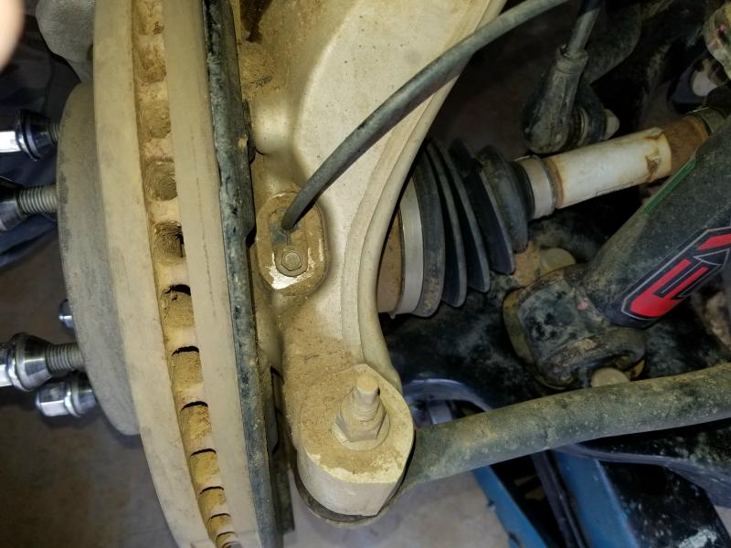
8. Remove ABS sensor from the top of the knuckle, use an 8mm socket.
Clean the dirt away from it if it’s dirty.
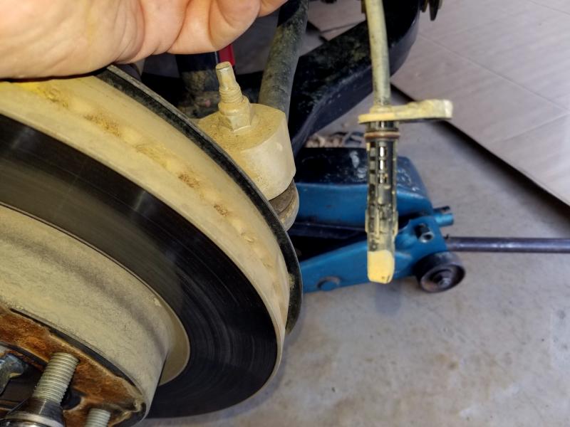
This is what it looks like when it’s out.
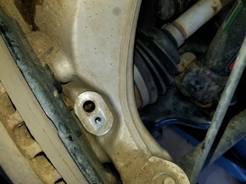
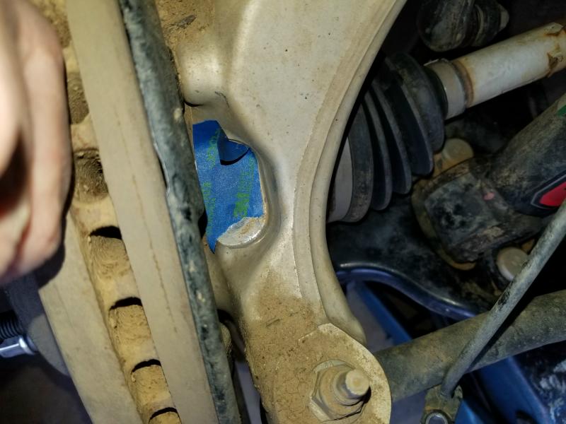
I stuck some tape of the holes to keep dirt from falling into them.
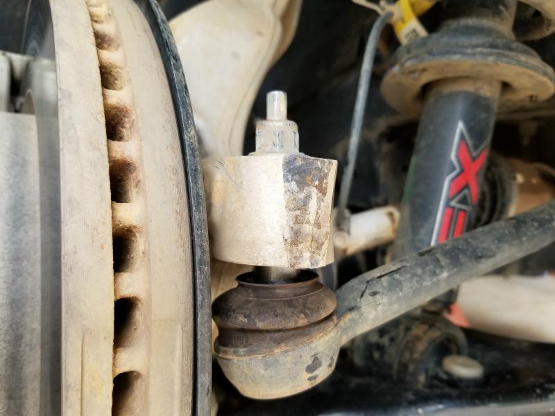
9. Loosen the nut on the tie rod end, using a 15mm socket, use a hammer to unseat the taper, striking the end of the knuckle, finish removing the nut.
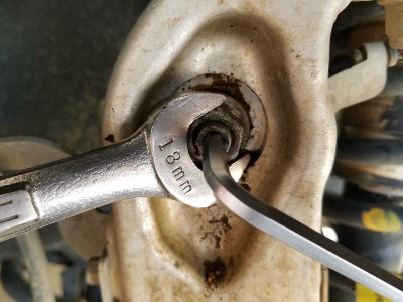
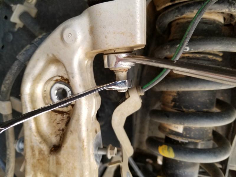
10. Loosen the nut on the upper control arm, using a 18mm wrench.
I had to use a wrench on the stud to keep it from turning while I loosened the nut with a wrench.
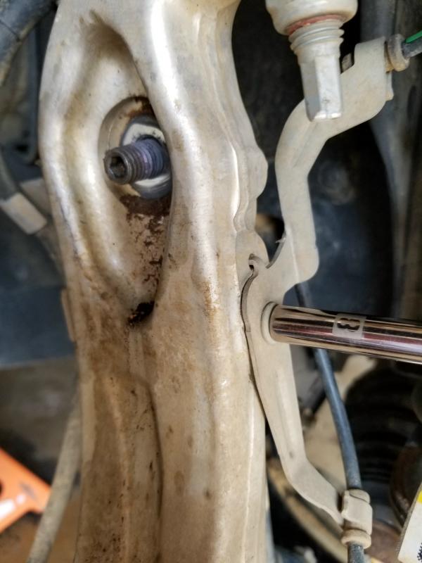
11. Unseat the taper between the upper ball joint and the knuckle, strike the front of the knuckle using a hammer to release the taper, remove the ball joint nut. Retain hardware for reuse.
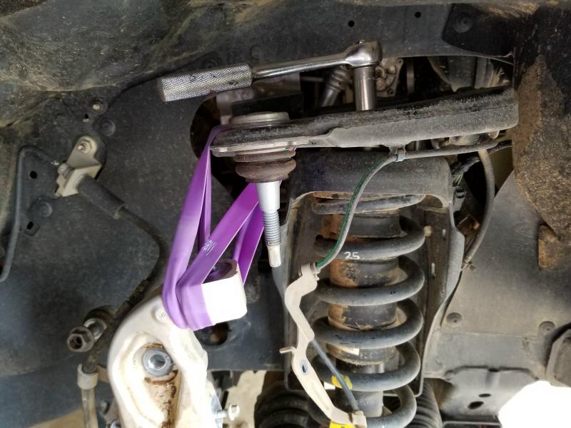
12. Let the knuckle relax back. Do not let the CV shaft pull out.
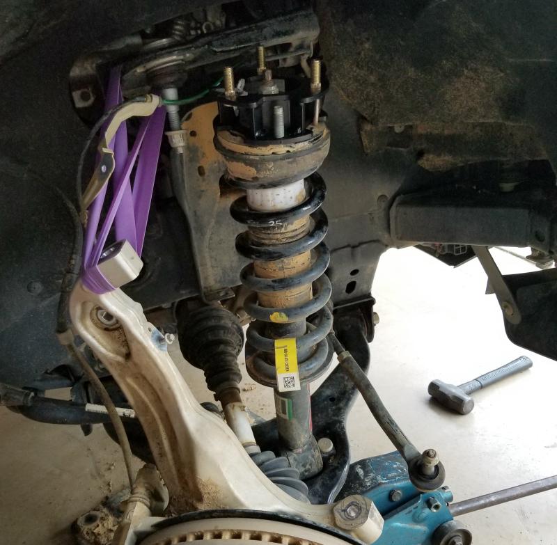
13. Remove the (2) strut nuts from the bottom of the lower control arm, using a 18mm socket. Retain hardware for reuse. Do not let the control arm drop to far down or the CV shaft may pull out.
14. Remove the (3) nuts on top of the strut hat, use an 18mm wrench. Retain hardware for reuse.
15. Remove the strut from the upper mount.
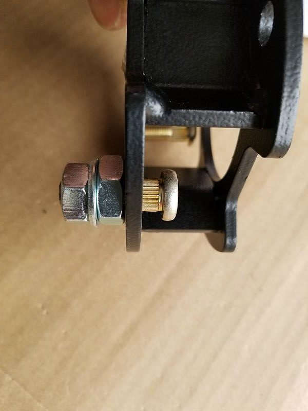
16. Using the supplied 10mm studs place each stud into the smaller sized holes in the strut spacer facing upward. Use the supplied 1/2” jam nut to slide over each stud to act as a spacer hold the 1/2” jam nut with a 3/4” wrench allowing you to pull the stud through the hole with the 10mm nut and a 17mm wrench, locking the stud into place. Remove the 1/2” jam nut and repeat on the other five studs.
17. Place the strut spacer on top of the factory studs, use factory hardware, tighten with a 15mm. Torque at 32 ft/lbs.
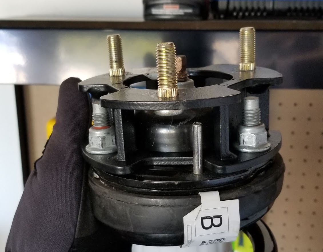
18. Place the bar pin of the lower strut mount into a vise and hand start the nuts. Next use a hammer and knock the studs out of the bar pin. Retain factory hardware for reuse.
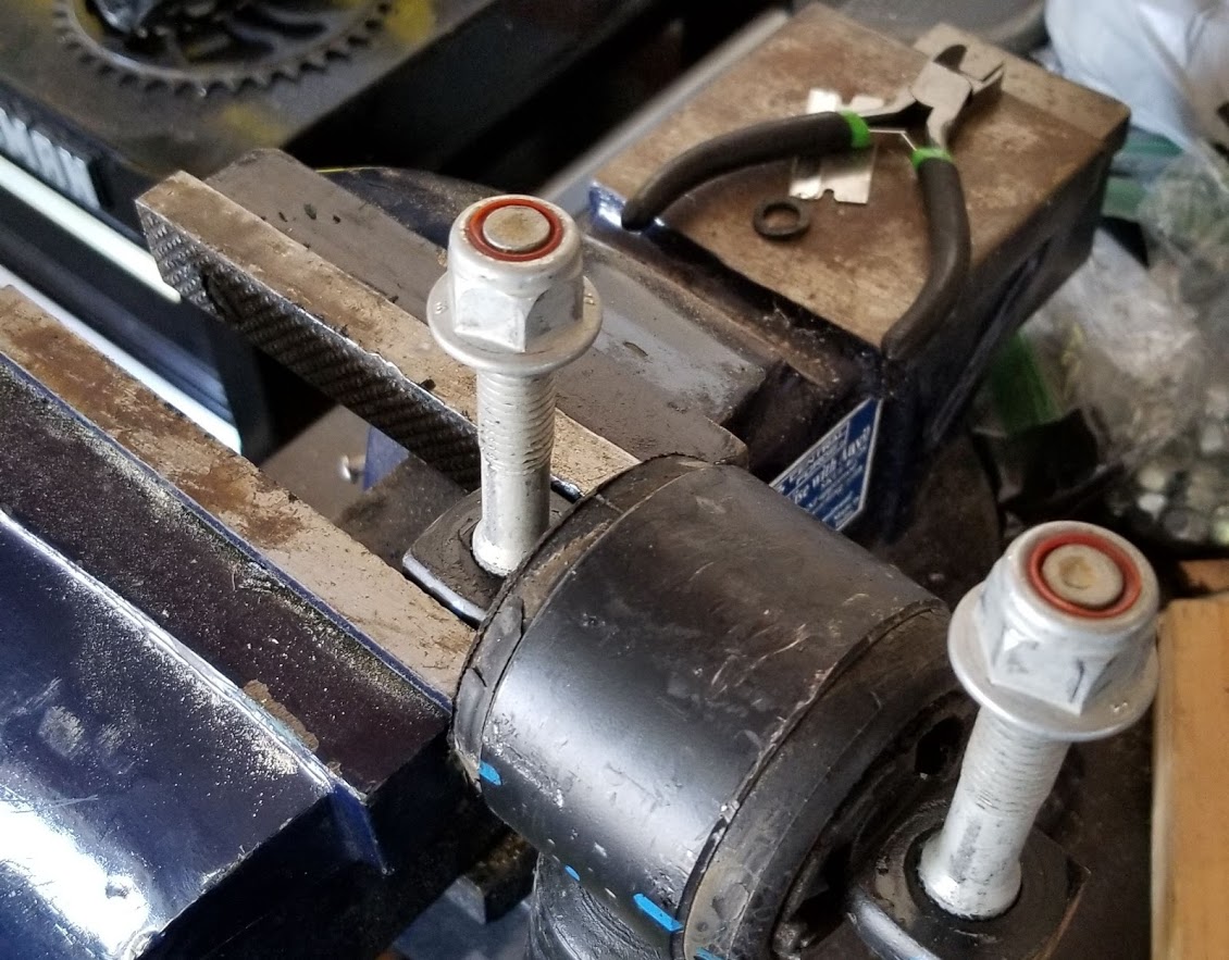
NOTE: You may want to use a press if you have one:
19. Install the strut assembly in the factory mount with the supplied 10mm nuts/washers &lock-washers on the upper mount.
20. Align the lower mount of the strut with the lower control arm mount. Install the factory studs back into the barpin on the lower mount of the strut.
21. It may be necessary to hit the top of the studs with a hammer to seat the splines, tighten the factory nuts with a 18mm. Torque at 78 ft/lbs.
22. Install the upper ball joint into the knuckle using the stock hardware. Hold the ball joint stud with an 8mm wrench and tighten the nut using a 15mm wrench. Torque at 32 ft/lbs.
23. Tighten the (3) upper strut nuts, use a 17mm wrench. Torque at 32 ft/lbs.
24. Install the ABS sensor into the knuckle, use the bolt that was removed, tighten using a 8mm socket. Torque at 8 ft/lbs.
25. Re install the ABS wire bracket onto the front of knuckle, use a 8mm socket to tighten, Torque at 8 ft/lbs.
26. Install the brake line bracket onto the rear of the knuckle, use a 10mm socket to tighten. Torque at 22 ft/lbs.
27. Re install the tie rod into the knuckle using the stock hardware, Hold the ball joint stud with an 8mm wrench and tighten the nut using a 15mm wrench. Torque to 32 ft/lbs.
28. Repeat steps 6-27 on the opposite side of the vehicle.
29. Re connect the sway bar link into the knuckle on the drivers and passengers side using the stock hardware, use a 18mm socket to tighten. Torque to 32ft/lbs.
30. Re connect the (3) EPAS (Electronic Power Assist Steering) Plugs.
31. Re install the skid plate in the original location, use the removed hardware in the rear, tighten using a 15mm socket. Torque to 32ft/lbs.
Post Installation Instructions:
1. Check all fasteners for proper torque. Check to ensure for adequate clearance between all rotating, mobile, fixed, and heated members. Verify clearance between exhaust and brake lines, fuel lines, fuel tank, floor boards and wiring harness. Check steering gear for clearance. Test and inspect brake system.
2. Perform steering sweep to ensure front brake hoses have adequate slack and do not contact any rotating, mobile or heated members. Inspect rear brake hoses at full extension for adequate slack. Failure to perform hose check/ replacement may result in component failure.
3. On some vehicles the front lower skirting will need to be trimmed if using certain wheel /tire combinations and with heavy offset wheels. Trim only as needed.
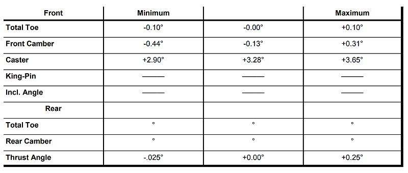
4. Have a qualified alignment center align the vehicle immediately. Realign to specifications in the chart below.
5. Perform head light check and adjustment to proper settings.
6. Check and retighten wheels at 50 miles and again at 500 miles.
7. All kit components must be retightened at 500 miles and then every three thousand miles after installation. Periodically check all hardware for tightness.
8. Install “Warning to Driver” decal on sun visor Note: Installation of larger tires will require speedometer recalibration.
Alignment Specifications:
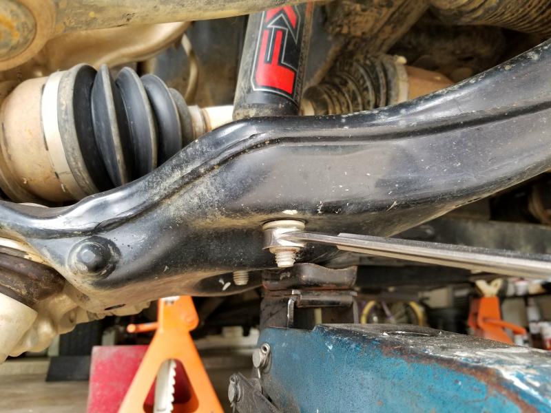
Note About The Lower Strut Studs:
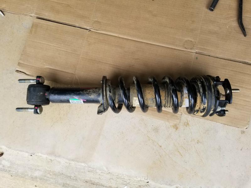
You are not going to be able to remove the bottom studs in the strut unless you secure the strut in a vice and drive them out with a hammer. That, or use a press.
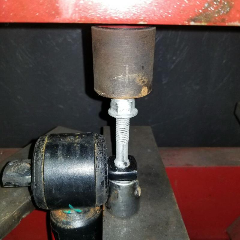
This is what the strut looks like (below) sitting in its lower mount with the studs still in place. You can’t push the lower control arm down far enough to get the strut to fit under the upper control arm. And if you do, you’ll most likely pull the axle shaft out. If you install the top of the strut into the upper control arm, you’ll never get the bottom in place because the lower studs won’t clear the lower control arm.
With the lower studs removed, you can insert the top of the strut back into the upper control arm, position the bottom of the strut into the lower control arm, and then re-install the lower shock studs and nuts and bolt it up.
Link
Rough Country 2.5-Inch Leveling Kit For 2019 Ford Ranger 4WD
Related Articles
Rough Country Leveling Kit – 2019 Ford Ranger 4×4
Installing A Skyjacker 3.5-Inch Lift – 2021 Ford Ranger
3.5-Inch Suspension Kit Buyers Guide
6-Inch Suspension Lift Buyers Guide
2019-2023 Ford Ranger Off-Road Builders Guide
2019-2023 Ford Ranger Wheel & Tire Guide
Last updated:
About The Author
Jim Oaks is the founder of TheRangerStation.com, the longest-running Ford Ranger resource online since 1999. With over 25 years of hands-on experience building and modifying Ford Rangers — including magazine-featured builds like Project Transformer — Jim has become one of the most trusted authorities in the Ford Ranger off-road and enthusiast space.
Since launching TheRangerStation.com, Jim has documented thousands of real-world Ranger builds, technical repairs, drivetrain swaps, suspension modifications, and off-road adventures contributed by owners worldwide. TheRangerStation.com has been referenced in print, video and online by enthusiasts, mechanics, and off-road builders looking for practical, and experience-based information.