Ahhh the short block. This has almost been its own story, and a full review will be in a separate thread once I've concluded conversing with the shop it came from about it. I don't feel it appropriate to do a proper review untill they've at least had a chance to respond to my findings. Due to the nature of this project, both my intent to thoroughly review this and that it's host is going to be the subject of a book, due to their warranty policy, warranty repair was never going to be an option for this engine.
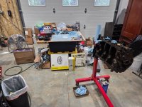
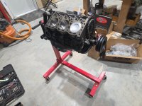
So lets dive in. It arrived, well packed, wrapped in plastic and drenched in oil. I took it off the palate, hung it from the stand, hung the pan by two bolts, wiped the excess oil from the painted surfaces and put the balancer on loose to rotate it.
The first thing I noticed was that the inside of the area where the filter housing was attached was covered in paint.
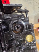
I was a little miffed but thought they must've just forgot to tape it off. Stuff happens. Whatever, I figured I'd just float it out with acetone and flush the galleries with brakleen and shop air. On the back of the block one freeze plug wasn't fully flush. I don't know if its sealed tight or not, but even though they used sealant I'll be redoing it for the sake of my own sanity, cuz its behind the flywheel.
The next thing I noticed, was that oil squirters in the con rods were facing the outer sides of the block. I took pause for a minute, and thought that it would make more sense for them to squirt the downward facing side of the cylinders, as the oil would flow from there down. I consaulted the manual, and found nothing. I bought the official Ford service manual, and found nothing. I scouered Sven Pruett's book and eventually found a generalization, that the anti rotation tabs of the rod bearings should all be on the drivers side of the block, aiming the oil squirters to the passenger side for all six pistons. I then googled, and found nothing. I then remembered I had a junkyard engine torn appart and spread across my shop floor. The headgaskets of that engine were 87 dated, and the con rods did indeed all point the squirters and anti rotation tabs as Sven's book describes. This indicated that the three con rods of the left bank were backwards.
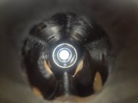
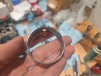
Appart it came, to include the cam. I had a look inside with Snek Cam to check alignment of the oil galleries. Not only, were the #2 and 3 bearing's oil hole not aligned to the head supply galleries AT ALL, but all four were so badly scratched and gouged that the bearings looked like they were plucked out of a bucket of gravel that had been stored in the hopper of a rock processor. I bought a cam bearing in/unstaller tool, and knocked them out to replace with NOS Ford. It wasn't untill I was halfway through installing them that I noticed, that NOT ONLY was all of the above wrong, THE #3 AND #2 BEARINGS THEY USED WERE
MISSING TWO OF THE THREE OIL HOLES!!!!!!&#^%@%@
*inhales deeply*
Anyway, I put the new cam bearings in very carefully, absolutely nailing the gallery alignment (snek cam pics later):
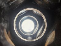
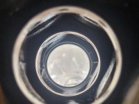
I set the depth of the #1 bearing to .040
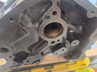
And installed the cam:
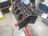
It did not turn freely

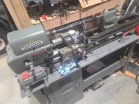
I took the cam back out, wiped it off, and put it in the lathe between centers as shown in the previous post, finding 2.5 thou and 3 thou of runout on bearing journals 2 and 3 respectively. After some research, I noticed that the Ford manual did give a runout spec of no more than 5 thou. I figured it must've been fine. My bore mic doesn't go small enough to get inside of the cam bearings, and my telescoping gauges arent long enough to get to #2 and #3 but the size change from uninstalled to installed on #1 and #4 was identical and put clearances in spec on the very loosest end of the specified range. The middle two bearings measured to do the same before they were installed. I thought perhaps something got in there and caused a bind. I wiped everything clean with acetone and tried again. Slightly better, but no joy. Then it occured to me that I couldn't get to the #2 and #3 bearings themselves with assembly lube. I was relying on what was left on the journals after they had passed through the other bearings. I took my assembly grease and injected it down the oil galleries that supply each head and the cam freed up immediately. I cleared the two galleries with air, and it stayed free. . . Ideal? Who knows. Im open to suggestions, but I'd rather not mess with it further.
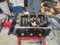
Next I plastigauged the crank, its all the way loose in the specified range in the manual, but Mr. Pruett's book says its good to be on the loose side. Took the crank back out, applied assembly grease, and torqued the mains back on for now. I still need to apply sealant to the rear and seat the thrust bearing flush again. Since I had decided to check everything after finding my obliterated cam bearings (and I'm leaving a whole lot out here btw) I had the shop leave the rings off the pistons for me to measure gap. They were all identical, at the widest open end of the spec, and the (iirc) second rings were all 1 thou over spec. . . .
To be continued. . .