CaymenBlueLongRanger
New Member
- Joined
- May 19, 2013
- Messages
- 10
- Reaction score
- 1
- Points
- 3
- Vehicle Year
- 1996
- Make / Model
- ford
- Transmission
- Manual
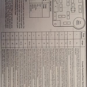
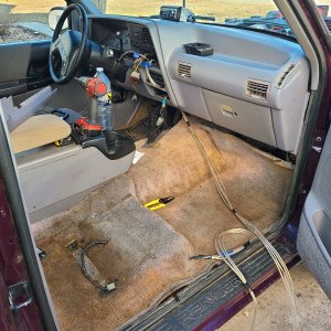
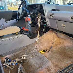
I have a 1996 Ford Ranger 4.0 5 speed long-box standard cab 2 wheel drive truck with no power windows. mirrors or locks. The speedometer has recently stopped working and I have found something that does NOT make any sense. with the ECU plug connected or disconnected and the engine-cab connector connected I get a DC voltage reading of about 8.5 volts with the key off, rising to 12 volts with the engine running, and at the same time an AC voltage - cannot remember the base when not running, but rising to 15+ volts with the engine running. When I disconnect the harness to the cab the voltage goes away. The speed censor gives me about 2.6 volts AC when spun by my Milwaukee battery drill and the signal can be read between pins 33 and 58 on the ecu - either connected or disconnected - as long as the cab harness is disconnected In the wiring diagrams the only thing these wires connect to in the cab are the speedo and the CTM / GEM. It would also connect to the speed controller amplifier/servo assembly if the truck had cruise control (which it does not) Pulling every fuse, one at a time, from the fuse panel in the end of the dash panel does NOT kill either the AC or DC voltage across the speed sensor. Is there any function or misfunction of the CTM/GEM on this vehicle that could/would feed either an AC or DC voltage back to the ECU/speed sensor circuit????
There are no codes and no CEL, but there is also no VSS signal most of the time. Sometimes I get a speed signal to my ScanGuage -(and a vss signal to the ECU) but no speedo. Sometimes I also get a speedo reading - sometimes erratic and occasionally steady (and accurate) - but most of the time NOTHING.
The problem all started immediately after having a lean engine code CEL and replacing the MAF sensor and EGR valve and tube. I will be replacing the speed sensor in the transmission because the housing was corroded and it came out in 2 pieces when I removed it to check it - but electrically it tests OK at just over 250 ohms and it puts out the expected signal when spun. Continuity in the engine main harness and the transmission sub-harness all checks out. I did add a ground to the pink and orange wire at pin 33 of the ECU - this was before finding out I had the AC and DC voltages across the speed sensor circuit.
Anyone with experience in this realm??? NOTE -it is a 1996 - not a 1995 or older or 1997 or newer. It does NOT use the ABS speed sensor on the rear axle for the speedometer, nor does it have a speedometer cable. It does NOT have a frequency converter to convert to 4000hz from 8000. I have not disconnected the plug from the back of the speedo or from the GEM/CTM yet to see if the voltage goes away. I have heard there is a CTM reset procedure involving disconnecting the battery and shorting the cables to drain charge from the CTM. I have not done that either (I got rained out). Hopefully I can find a knowlegeable Ford tech with an explanation/solution. (I am a retired auto tech - mostly Toyota experience pre 2K)


