• Welcome Visitor! Please take a few seconds and Register for our forum. Even if you don't want to post, you can still 'Like' and react to posts.

BR's 97 Supercab Build


BR

New Member
Joined
Oct 12, 2018
Messages
15
Reaction score
13
Points
3
Location
Milwaukee, WI
Vehicle Year
1997
Make / Model
Ford
Engine Type
4.0 V6
Transmission
Manual
2WD / 4WD
4WD
Total Lift
6
Tire Size
35
Longtime listener, first time caller. Forum has been helpful to be since I was 16 and had my first reg cab flareside Ranger.
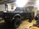
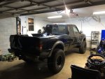
Always wanted to build out another Ranger after I finished school and became an "adult".... so here goes.

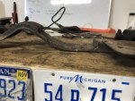
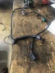
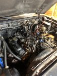
Originally I found a 96 2.3L 4x4. Looked ok, had some idle issues. As I dug in deeper to it, this Ohio farm truck was pretty bad. I ended up pulling the good parts: manual T case, shifter, extension housing. Then scrapped everything else.

IMG_3672.JPG


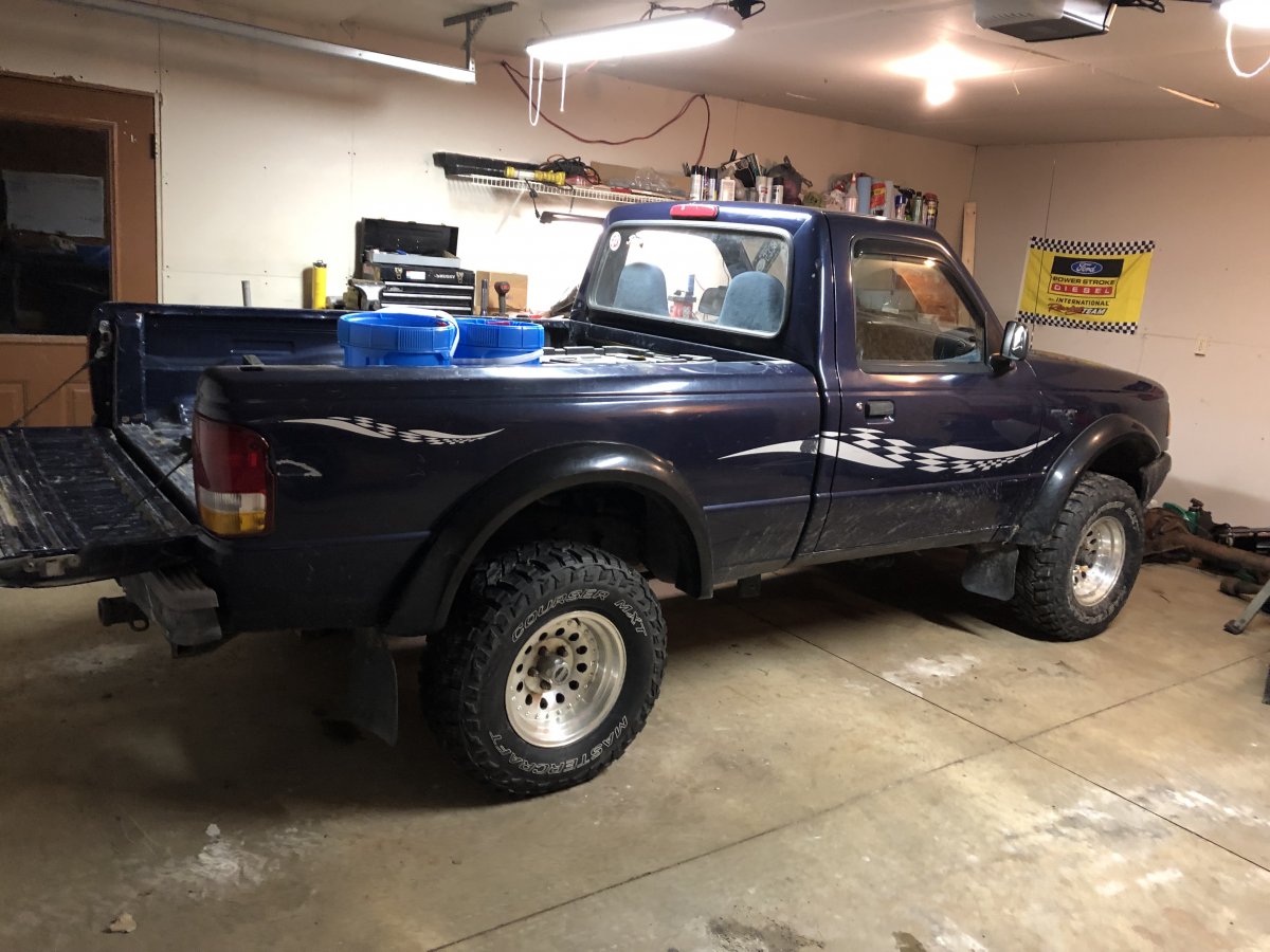
In Spring 2019, when I knew the 2.3L was going to go away, I knew I needed something better to start with.
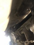
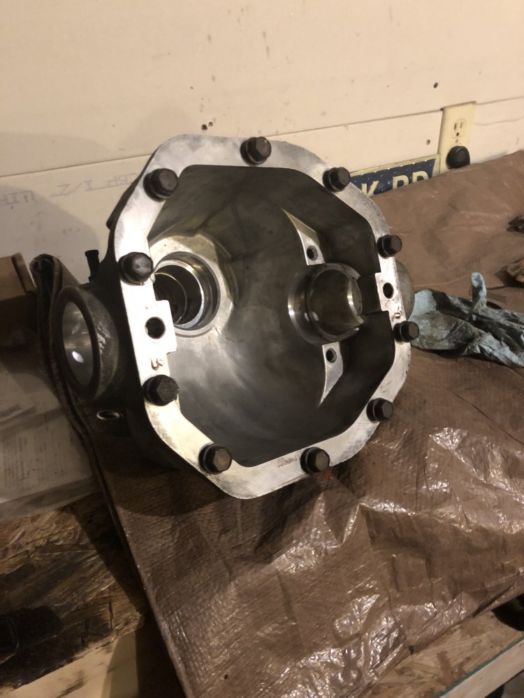
Before I scrapped the truck, I actually was building axles for it. Bought a D35 front chunk with beams and bought a 31spline 8.8 from a Sport Trac.
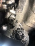
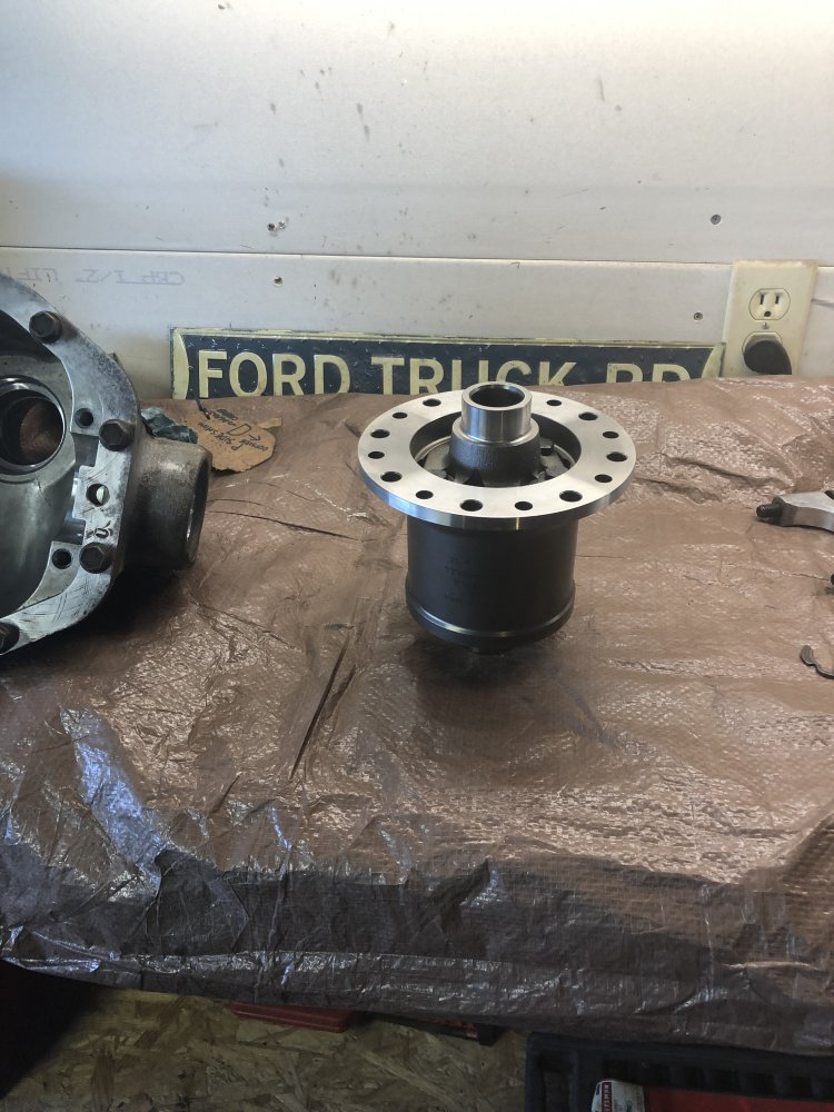
Specs were 5.13 gears, found a TrueTrac listed for a D35 rear application and flipped the worm gears for a "front" usage. Installed a Grizzly locker in the rear.
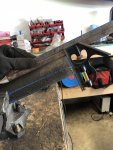
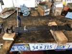
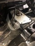
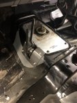
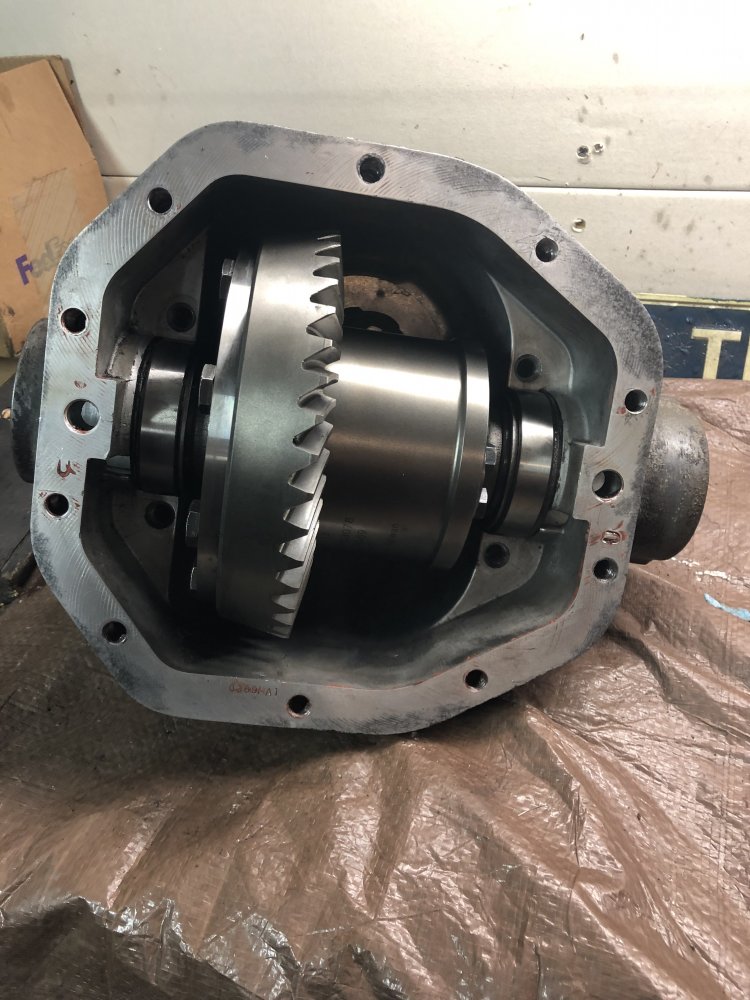
D35:
IMG_3494.JPG

IMG_3497.JPG

IMG_3875.JPG

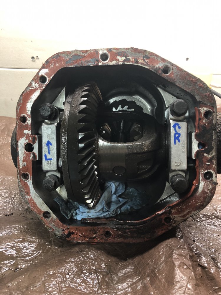
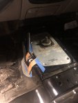
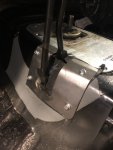
The TrueTrac carrier:
IMG_3883.JPG

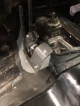
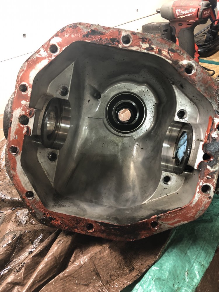
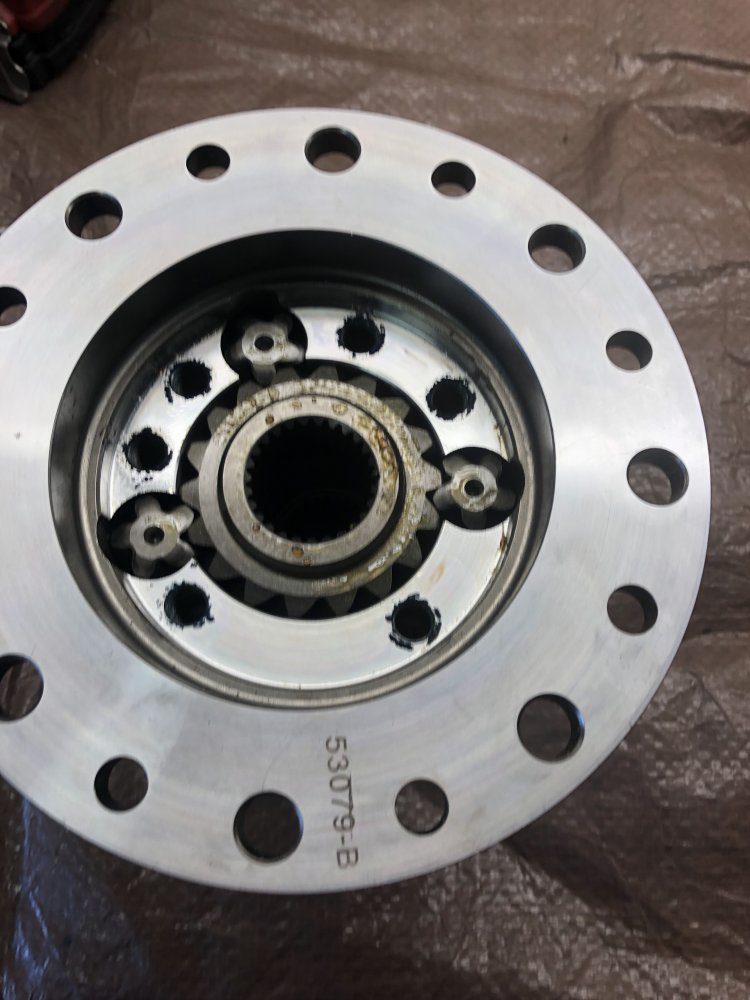
Pulled off the side cap that holds the gears in:
IMG_3884.JPG

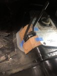
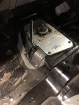
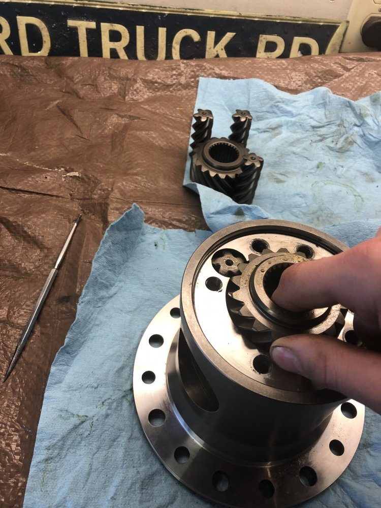
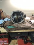
Pull the gears out and move them from one side to the other. Saw this on a Land Rover or Toyota forum where they claim it changes the bias ratio since "reverse" is now "forward":
IMG_3887.JPG

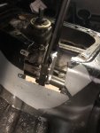
Gears mocked up for getting shims right:
IMG_3893.JPG

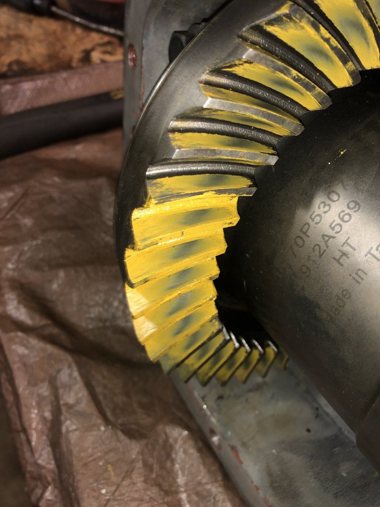
Checking backlash and pattern:
IMG_3905.JPG

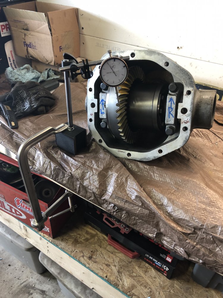
Have 10 different pattern pictures, so not sure if this was the final one. I think it was:
IMG_3927.JPG

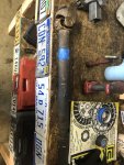
EDIT: while I used a crush sleeve on the rear axle, the front was difficult. Didn't have enough snuff on the air gun and couldn't lock the housing down enough to torque it manually. Used a solid pinion spacer instead. Worked great! Bought it from Ratech.
I think to save space I'll drop the 8.8 pics in the next post.
 

Attachments

Last edited:


BR

New Member
Joined
Oct 12, 2018
Messages
15
Reaction score
13
Points
3
Location
Milwaukee, WI
Vehicle Year
1997
Make / Model
Ford
Engine Type
4.0 V6
Transmission
Manual
2WD / 4WD
4WD
Total Lift
6
Tire Size
35
Got a 31 spline 8.8 from a 02 Sport Trac that a guy was parting out. Fortunately, this was the one year of drums..easy enough.
IMG_3508.JPG

Stripped:
IMG_3708.JPG

5.13s and the Grizzly Locker:
IMG_3715.JPG

Tightening the ring gear bolts trick:
IMG_3719.JPG

Checking the backlash and pattern:
IMG_3721.JPG

Again I don't remember if this was the final pattern pics but close enough:
IMG_3770.JPG

IMG_3771.JPG

Housing then sat around while I scrapped the 2.3L truck and looked for the Supercab I would eventually end up with:
IMG_3876.JPG
 

BR

New Member
Joined
Oct 12, 2018
Messages
15
Reaction score
13
Points
3
Location
Milwaukee, WI
Vehicle Year
1997
Make / Model
Ford
Engine Type
4.0 V6
Transmission
Manual
2WD / 4WD
4WD
Total Lift
6
Tire Size
35
I lost a bunch of images from when I bought the truck and initially started working on it. 97 Supercab, black, 4.0L, M5OD, 256k miles? Bought it from a lady in WV that drove it when she was college age, now had kids and stopped driving it. Truck has obviously been repainted, quality a little suspect. Can see runs in the paint, etc.
Only picture I still have was driving back with it on the trailer, and it's out the window of the tow pig I had at the time..whatever:
CILP6447.JPG


Before I started "building" the truck, went through some drivetrain issues. Truck was throwing O2 sensor codes, needed a new MAF and plugs. Fought the clutch setup a fair amount, as it would block me out of 1st and rev. Dinked around with the clutch lines. Ended up being related to the flywheel/clutch/pressure plate replaced later.
Threw a new master cyl at it:
HMZL5113.JPG


Found a guy parting Rangers near work and picked up two one pc driveshafts from him. A steel and an aluminum one. Here's how I modified the carrier bearing xmember.
Trimmed the area it needed to clear the driveshaft:
IMG_1556.JPG

IMG_1559.JPG

IMG_1564.JPG

IMG_1567.JPG

IMG_1569.JPG

IMG_1573.JPG

IMG_1574.JPG
IMG_1576.JPG
 

Attachments

BR

New Member
Joined
Oct 12, 2018
Messages
15
Reaction score
13
Points
3
Location
Milwaukee, WI
Vehicle Year
1997
Make / Model
Ford
Engine Type
4.0 V6
Transmission
Manual
2WD / 4WD
4WD
Total Lift
6
Tire Size
35
At this point, tore the truck down pretty far. Took out all the suspension and hacked off all the brackets. Ordered a Duff lift with the extended radius arms and deaver leafs. No pictures of it in "hover truck" mode. At the same time, I pulled the transmission since I had easy access.
IMG_5420.JPG


Popped open the top cover of the trans to just give it a once over, and found 5th gear was broken....
Stripped the whole transmission to refresh it. Too bad I scrapped the 2.3L as I could've used the gearset from it for a deeper 1st gear.
Pics start after the whole transmission was stripped. Starting with the bare mainshaft:
IMG_5002.JPG


Mainshaft halfway assembled:
IMG_5013.JPG


I found the front bearing race of the mainshaft was pitted. Me, being an idiot, decided it would be fine to hit it with emory cloth and call it good. Ended up being noisy from the second I put it in. This truck isn't really a driver, so I'm just living it it. Pic of the pitting:
IMG_5014.JPG

IMG_5015.JPG

IMG_5016.JPG


Rebuilt countershaft in:
IMG_5017.JPG


Mainshaft going back in:
IMG_5020.JPG

Input, main, and counter shafts all in the case:
IMG_5053.JPG

5th and rvs put together:
IMG_5087.JPG


New flywheel, clutch and pressure plate. The issue (I'm going from memory) was the clutch flatness. I could be wrong, but it was something like that. Regardless, new parts have it shifting great now.
IMG_5404.JPG

IMG_5405.JPG


And in it goes
IMG_5421.JPG
 

BR

New Member
Joined
Oct 12, 2018
Messages
15
Reaction score
13
Points
3
Location
Milwaukee, WI
Vehicle Year
1997
Make / Model
Ford
Engine Type
4.0 V6
Transmission
Manual
2WD / 4WD
4WD
Total Lift
6
Tire Size
35
Out of order post, but figured it would make more sense to have it relate to all T case stuff.
Had the electronic T case from the 97, had the manual T case from the 96 I scrapped, and another electronic T case from the 02 Sport Trac.
Initial plan was to make a doubler from Behemoth using the Sport Trac's guts combined with the manual T case. Reviews and feedback from other forums steered me away from going that route.

Ended up going this way:
IMG_5282.JPG

IMG_5283.JPG


Atlas II, 4.3 low range. Spec'd the yokes to work with the OEM driveshafts. Have not seen many run this case, so I'll go into a little more detail on how I made it work.
Test fitting the case, remember no body lift:
IMG_5428.JPG

Overall it was pretty close! Can't remember if I needed to make room before I got to this point. You will need to modify the floorboard.
IMG_5429.JPG


With the Duff lift, the front cleared the trans crossmember just fine:
IMG_5432.JPG

Clears the driver frame rail fine:
IMG_5435.JPG


The areas needing most work was the shift tower area of the Atlas. You can see the sharpie marks below to give an idea. I used a rubber faced deadblow to get that out of the way. The breather barb is on top of the shift tower and is still very tight to the floorboard. Driving around it seems to be just fine. YMMV
IMG_5436.JPG

IMG_5437.JPG


The shifter mechanism will need some work to clear as well, and obviously cut the floor. Here's a mockup pic before the chop:
IMG_5446.JPG

Here's a pic of the T case out and marks of where I was pushing the floor around. Maybe makes sense, maybe doesn't:
IMG_5473.JPG

IMG_5474.JPG

IMG_5475.JPG

IMG_5476.JPG


At this point, the thing physically fit. Next post will be all the other stuff to make it work! Shifter, driveshafts, speedometer.
 

Attachments

BR

New Member
Joined
Oct 12, 2018
Messages
15
Reaction score
13
Points
3
Location
Milwaukee, WI
Vehicle Year
1997
Make / Model
Ford
Engine Type
4.0 V6
Transmission
Manual
2WD / 4WD
4WD
Total Lift
6
Tire Size
35
For the driveshafts to make the Atlas work, here's what I did.
The front to rear yoke dimension is so close compared to the factory case. When I flipped the perches on the 31 spline 8.8, I used the Ruffstuff swap kit. The perches supplied actually have 3 centering pin holes (factory, WB - 1", WB + 1"). I tried in the factory WB pin, and the OEM 1pc driveshaft was compressed to the maximum. Popped the axle back to the WB +1" pin, and voila! Can use any 98+ driveshaft.
IMG_5438.JPG

IMG_5439.JPG

IMG_5440.JPG

IMG_5441.JPG


For the front driveshaft, I bolted the T case side in and cycled the beam. Measured where I was in relation to the slip yoke position. Ended up needing to shorten it.
I didn't really have a concern about shortening it, and it vibrating too badly. The most correct way would be to have a driveshaft shop do it, but I've had it up to 65-70mph with the hubs locked out and seems ok to me.
Anyway, here's the pics.

Doing the math before the big chop:
IMG_5765.JPG


Before surgery:
IMG_5756.JPG

The big chop itself:
IMG_5758.JPG

IMG_5759.JPG


Making sure the ends are square:
IMG_5761.JPG

IMG_5762.JPG


Clamped the ends into C channel to line them up. The lines are to make sure I kept everything phase:
IMG_5764.JPG

Metal glued back together:
IMG_5766.JPG


Alright, now on to making the shifter work!
 

Attachments

BR

New Member
Joined
Oct 12, 2018
Messages
15
Reaction score
13
Points
3
Location
Milwaukee, WI
Vehicle Year
1997
Make / Model
Ford
Engine Type
4.0 V6
Transmission
Manual
2WD / 4WD
4WD
Total Lift
6
Tire Size
35
Making the shifter work isn't as simple as using the manual T case cutout from the factory. Due to the angle, the shifter assy wants to pass through the angled portion of the tranny tunnel.
The inspo:
IMG_5499.JPG


I just started cutting and opening it up as I went, careful to not go too far.
IMG_5507.JPG

IMG_5508.JPG

IMG_5509.JPG

I don't think it's possible to cut a tiny hole just to pass the shift tower through. I decided to make a shifter plate.
Here's my CAD:
IMG_5510.JPG

Here's the hole in the tunnel in its entirety:
IMG_5528.JPG

Plate was a little difficult to make being some compound angles going on. I think this is OK enough:
IMG_5531.JPG


I needed something to seal the shifter plate and the floorboard. I cut up one of those non-slip kitchen placemats.
IMG_5535.JPG


Alright, shifter plates installed.
IMG_5534.JPG


I used the boots and self tappers from the Atlas install kit. Placing the self tappers on the removable shifter plate.
To make it fit over the carpet, I just hacked a big hole. I'm sure there are WAY better ways to do this, but I really didn't care.
Here's the money shots:
IMG_5694.JPG

IMG_5696.JPG
 

Attachments

BR

New Member
Joined
Oct 12, 2018
Messages
15
Reaction score
13
Points
3
Location
Milwaukee, WI
Vehicle Year
1997
Make / Model
Ford
Engine Type
4.0 V6
Transmission
Manual
2WD / 4WD
4WD
Total Lift
6
Tire Size
35
Onto the final chapter of the Atlas install, the speedometer. Had a few options how one could do this:
1. Atlas gives you the phone number to a speedo cable shop that will build a custom one-off adapter to go from the Jeep style speedo hole, drive a cable stub, and terminate into a Ranger style speedometer hole. This was a non-starter for me as its custom parts.
2. I thought about deleting the ABS and repurposing the VSS signal from the axle. However it didn't seem like any speedo adapters would be able to pulse divide far enough to get it within range of what the speedometer requires. (I can provide more tech info as a reply if anyone wants it)
3. Use the Jeep TJ speedo sender. The challenge with this is TJ senders are a 5V square wave. Rangers use a 2 wire PM sensor that generates a -2V to 2V sine wave. I wondered if the sampling point of the speedo would accept a square wave, but decided to buy a Dakota Digital speedo adapter.

Here's how I applied it.
First I had to get power to the Dakota Digital. I didn't want any additional wires or separate fusing. Through the EVTM I found that manuals still have the Overdrive Off light wiring the automatic uses! Single 12V wire, already fused, just hanging out under the dash.
IMG_5626.JPG

I decided to mount the Dakota Digital on the steel plate that goes behind the lower dash panel. I reused a pigtail I hacked off the scrapped Ranger.
IMG_5628.JPG


I didn't want to hack another hole in the floor. I had a realization that since I don't have an electric T case anymore, I have a free harness with a grommet already.
Here is the interior harness I made. On the left is the plug to go into the Dakota Digital. Can see the ground and power wires that go under the dash.
IMG_5629.JPG


Here's the engine side harness. I had to split out the Signal + and Reference wires. The wires make a loop. Come out of the TJ sender -> into the Tcase plug in the engine harness -> into the interior harness that goes up to the Dakota Digital box -> the modified speed signal goes back down the interior harness -> into the engine harness through the T case plug
IMG_5630.JPG

The whole harness to get the idea:
IMG_5632.JPG


Here's the Dakota Digital all powered up. There is a simulation mode where I can send the cluster a fixed frequency (33Hz/22mph in the pic):
IMG_5633.JPG


One HUGE thing to note is the pull-up resistor settings in the setup of the Dakota Digital box. On my first drive I noticed I had no speed signal. I found out the pull up resistor was set to OFF. Once I turned the pull-up resistor to ON, everything worked fine.
 

Attachments

BR

New Member
Joined
Oct 12, 2018
Messages
15
Reaction score
13
Points
3
Location
Milwaukee, WI
Vehicle Year
1997
Make / Model
Ford
Engine Type
4.0 V6
Transmission
Manual
2WD / 4WD
4WD
Total Lift
6
Tire Size
35
For the suspension, it was fairly straight forward. Installed the Duff 6" extended radius arm kit. I will be honest the fit up I was not impressed with. I didn't think the instructions were impressive either. I also made a pretty big mistake on the install. The lettering on the extended radius arms was upside down - meaning when I installed with the lettering up, the radius arms were actually flipped! Didn't realize this until the coils fit all weird and the shocks were at minimum travel.

Assorted install pics
IMG_5717.JPG

I think the Duff kit was designed around trucks with AC. Mine doesn't and the dual shock setup wouldn't clear the passenger side blower/air box. I wanted to keep that and hacked up the shock bracket to fit a single shock:
IMG_5357.JPG


IMG_5718.JPG

Got the rear mocked up:
IMG_5720.JPG


Front going in. Again - I know the radius arms are flipped. At this point I did the C-clip eliminator using the external spring on the passenger shaft with the clamp collar.
IMG_5789.JPG

IMG_5797.JPG

IMG_5803.JPG


OK the front looks good:
IMG_5799.JPG


Now for the rear. Needed to weld the perches. Set the pinion angle.
IMG_5813.JPG


Burned in the perches:
IMG_5822.JPG

IMG_5824.JPG

Welded the shock brackets on (this was before the perches looks like):
IMG_5816.JPG

Primered
IMG_5840.JPG

Installed the discs:
IMG_5826.JPG

Welded little brackets to mount the explorer soft lines. After this pic, I ditched the driver side for two passenger side lines. Used a standard T block instead.
IMG_5833.JPG

Installed into the truck
IMG_5930.JPG

IMG_5932.JPG
 

Attachments

BR

New Member
Joined
Oct 12, 2018
Messages
15
Reaction score
13
Points
3
Location
Milwaukee, WI
Vehicle Year
1997
Make / Model
Ford
Engine Type
4.0 V6
Transmission
Manual
2WD / 4WD
4WD
Total Lift
6
Tire Size
35
I had a set of 315/70r17 Grabber X3s from my Titan that I put maybe 1500 miles on.
Found a set of steelie 17" beadlocks for 5x4.5 from Sidetracked offroad. They are cheap but fit the bill. One actually had a leaky weld I had to repair. Found that out after I got the tire all together, so had to blow it all apart.
I used airsoft BBs to balance them. Found a dynabeads chart for weight and threw in about the same.
IMG_5650.PNG


IMG_5651.PNG

IMG_5652.PNG

IMG_5655.JPG

IMG_5658.JPG

IMG_5666.JPG
 

BR

New Member
Joined
Oct 12, 2018
Messages
15
Reaction score
13
Points
3
Location
Milwaukee, WI
Vehicle Year
1997
Make / Model
Ford
Engine Type
4.0 V6
Transmission
Manual
2WD / 4WD
4WD
Total Lift
6
Tire Size
35
At this point I was ready to back it out of the garage:
IMG_5990.JPG


Looks like I have some trimming to do:
IMG_5992.JPG

IMG_5991.JPG

IMG_5998.JPG

IMG_6001.JPG


After this point, I ended up moving to WI - so the truck sat in storage for 7 months.
 

BR

New Member
Joined
Oct 12, 2018
Messages
15
Reaction score
13
Points
3
Location
Milwaukee, WI
Vehicle Year
1997
Make / Model
Ford
Engine Type
4.0 V6
Transmission
Manual
2WD / 4WD
4WD
Total Lift
6
Tire Size
35
After pulling it out of storage, looked like below. Had it on rollers in storage. Put the X3s back on to see where I needed to trim. Also flipped the radius arms over to the correct orientation.
IMG_7152.JPG

IMG_7151.JPG

IMG_7068.JPG

IMG_7150.JPG


Front bumper was simple enough:
IMG_7604.JPG


On the back was somewhat more of a challenge. Here is what I decided to do (for better or worse):
IMG_7572.JPG

IMG_7574.JPG

IMG_7575.JPG

IMG_7590.JPG

IMG_7597.JPG

IMG_7623.JPG

IMG_7633.JPG


At this point I was ready to drive it. Drove alright. Definitely needed an alignment. Felt fine up to 60mph on the test drive.
Next to tackle was the ...white smoke... from the exhaust and do a few other things before taking it on a trip.
 

Attachments

BR

New Member
Joined
Oct 12, 2018
Messages
15
Reaction score
13
Points
3
Location
Milwaukee, WI
Vehicle Year
1997
Make / Model
Ford
Engine Type
4.0 V6
Transmission
Manual
2WD / 4WD
4WD
Total Lift
6
Tire Size
35
After test driving it, I knew I had some engine issues to sort out.
Figured I had the lower intake gasket leaking, as I didn't have any signs suggesting a blown headgasket.
IMG_7245.JPG


Did a leakdown test and found #6 cyl had a crack in the head.
Ordered a set of heads and went to town.
IMG_7439.JPG

New heads on. I tried doing this quickly and didn't replace lifters, or pushrods. May have came back to bite me, see next posts.
IMG_7441.JPG


IMG_7442.JPG

IMG_7479.JPG


After I got it all back together, everything was fine. Had a P0171 code again. Looked everywhere for it, figured a vac line or gasket. Nope. Tracked it back to the cheap MAF I replaced only 1.5 years earlier was underreporting airflow by 20%.
 

Attachments

BR

New Member
Joined
Oct 12, 2018
Messages
15
Reaction score
13
Points
3
Location
Milwaukee, WI
Vehicle Year
1997
Make / Model
Ford
Engine Type
4.0 V6
Transmission
Manual
2WD / 4WD
4WD
Total Lift
6
Tire Size
35
At this point, it is mid Sept 2021. Planned to take the truck to Marquette Michigan in October. I do heavy sweep for LSPR, a stage rally event part of the ARA series. Decided it would be cool to use the little Ranger. This post mostly odds and ends.
First item was to get it aligned. I decided to try my hand at doing it myself, and it worked out pretty awesome actually.
I took spare vinyl tiles I had in the house, and leveled out the floor where the truck was sitting. This way I knew my measurements were somewhat accurate.
IMG_7790.JPG

IMG_7792.JPG

IMG_7647.JPG

Then I used the following method:
1. With the truck on the ground (on the tiles), I used the digital angle finder to get my measurements of caster and camber.
2. I then would jack the truck up so I could access the adjusters by taking the tire off.
3. I would take a new camber and caster measurement. With the measurement from 1, I knew how far I needed to go to get in spec. I added that delta value to the values I measured in 3 while the truck was jacked up.
4. Once the adjuster was set, drop the truck down and jounce it. Remeasure.

Got the truck in spec. Went with max positive caster and camber, while trying to stay within the delta values Ford has in the service manual. I wasn't able to achieve the correct caster split, but it's pretty close. Drives straight and true.

Then needed to make mounts for two 2m antennas. Use these for communication during the event.
Dropped the headliner
IMG_7689.JPG


NMO holes drilled in the roof
IMG_7690.JPG


Then mounted some Lightforce 240s I had:
IMG_7831.JPG

IMG_7832.JPG


Truck out in the woods:
IMG_7843.JPG
 

BR

New Member
Joined
Oct 12, 2018
Messages
15
Reaction score
13
Points
3
Location
Milwaukee, WI
Vehicle Year
1997
Make / Model
Ford
Engine Type
4.0 V6
Transmission
Manual
2WD / 4WD
4WD
Total Lift
6
Tire Size
35
This post is the point where everything is caught up to the present.
The truck only made it one day (like 200 miles), mostly dirt, but some 55mph roads as well. Truck developed a miss, so we had to let the truck sit. I thought maybe coil/plugs, so we threw them at the truck in the hotel parking lot. Did not help things.
At this point we left it, and used buddy Sierra for the rest of the weekend.

Now I'm not certain what could have happened. Lifters? Did I jack something up putting everything back together? Have not even dug into it yet, been distracted with getting my daily TDI Jetta going again to save miles on the 2.8 Duramax in the winter.

I did come across a Passat TDI too cheap to pass up. Ended up parting the car out, and have an engine, harness, and ECU. Have seen others do a BHW TDI swap. Have not committed to going that direction just yet. Comments/suggestions are welcome.
 

Sponsored Ad


Sponsored Ad

Staff online

Members online

Member & Vendor Upgrades

For a small yearly donation, you can support this forum and receive a 'Supporting Member' banner, or become a 'Supporting Vendor' and promote your products here. Click the banner to find out how.

Truck of The Month


Shran
April Truck of The Month

Recently Featured

Want to see your truck here? Share your photos and details in the forum.

Follow TRS On Instagram

TRS Events

25th Anniversary Sponsors

Check Out The TRS Store


Sponsored Ad


Sponsored Ad

Sponsored Ad


Amazon Deals

Top