• Welcome Visitor! Please take a few seconds and Register for our forum. Even if you don't want to post, you can still 'Like' and react to posts.

91 2.9L TPS signal testing


Skooby

Member
U.S. Military - Active
Joined
Dec 13, 2020
Messages
41
Reaction score
34
Points
18
Age
51
Location
Oregon
Vehicle Year
91
Make / Model
Ranger
Engine Type
2.9 V6
Transmission
Manual
2WD / 4WD
4WD
Total Lift
4
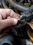
Truck will rev if throttle is opened slow, will pop and backfire if opened quickly. Trying to test the TPS and getting the 5V on the connector (disconnected) with the key on, not getting continuity to ground o. The other wire. With connector plugged in and key on seeing 5V on all three wires? Same result with 2 different TPS. Help? PCM ground?


franklin2

Well-Known Member
Joined
Dec 24, 2019
Messages
3,425
Reaction score
1,758
Points
113
Location
Virginia
Vehicle Year
1984
Make / Model
Bronco II
Transmission
Manual
Orange wire should be 5v. Green wire should vary when the throttle is moved. The other wire should be ground. What voltage do you get from the engine metal to the ground wire on the tps? Should be close to zero.
 

RonD

Official TRS AI
TRS Technical Advisor
Joined
Jun 2, 2012
Messages
25,363
Reaction score
8,370
Points
113
Location
canada
Vehicle Year
1994
Make / Model
Ford
Transmission
Manual
+1 ^^^

But reads more like the SPOUT wire is unplugged
SPOUT is the "vacuum advance" for spark system, it comes from the computer
You disconnect the SPOUT wire when setting the base spark timing, then need to plug it back in when done

The Distributor does RPM spark advance on its own, so it works OK if you slowly accelerate, the SPOUT is needed if you want quick throttle response
But same for TPS, it replaced the "accelerator pump" on carb engines
 

Skooby

Member
U.S. Military - Active
Joined
Dec 13, 2020
Messages
41
Reaction score
34
Points
18
Age
51
Location
Oregon
Vehicle Year
91
Make / Model
Ranger
Engine Type
2.9 V6
Transmission
Manual
2WD / 4WD
4WD
Total Lift
4
ok, finally got some time to play with the truck. Key on, connector unplugged- Top wire (red w/grey) +5v, bottom wire (brown w/white) +5v, middle wire (grey w/white) nothing. Key on connector plugged in +5v on all 3 wires regardless of throttle position. I should see continuity to ground on one if the wires and the middle should be varying from +1v to +5v.....
 

Attachments

franklin2

Well-Known Member
Joined
Dec 24, 2019
Messages
3,425
Reaction score
1,758
Points
113
Location
Virginia
Vehicle Year
1984
Make / Model
Bronco II
Transmission
Manual
I gave you the wrong wire colors didn't I? Brown/white is the 5v supply. Grey/white is the signal back to the computer. Grey/red is the signal return or "ground".

According to the diagram, you should also have a signal return or ground wire on the engine coolant temp sensor, the air charge temp sensor, and your MAP sensor. They all should have the grey/red or in some places it may be a black/white. All these different sensors having the same wire means there is a splice in the harness somewhere that splits this wire and leads it in all those different directions. Maybe you can take some readings on this wire at the other sensors, and see if you get a good ground anywhere in there and try to figure out where you are losing it.
 

19Walt93

Well-Known Member
Ford Technician
V8 Engine Swap
Joined
Nov 13, 2018
Messages
4,512
Reaction score
4,465
Points
113
Location
Canaan,NH
Vehicle Year
1993
Make / Model
Ford Ranger
Engine Type
V8
Engine Size
351
Transmission
Automatic
2WD / 4WD
2WD
Total Drop
3"
Tire Size
235/55R16
My credo
If you don't have time to do it right will you have time to do it over?
You want as close to one volt on the signal return wire at idle with the TPS plugged in, 5 volts on the signal return indicated WOT.
 

RonD

Official TRS AI
TRS Technical Advisor
Joined
Jun 2, 2012
Messages
25,363
Reaction score
8,370
Points
113
Location
canada
Vehicle Year
1994
Make / Model
Ford
Transmission
Manual
The grey/red wire runs to ALL the sensors, so test the grey/red on say the IAT(air temp) sensor, should be on upper intake drivers side 2 wires
Its a reference Ground, the computer uses pull down circuit, so not a true ground but should show as Ground

That comes from pin 46 on the computer
Pin 47 is signal return from TPS, just FYI

You could have a short between the two wires at TPS which is why you want to test at another sensor
 

Skooby

Member
U.S. Military - Active
Joined
Dec 13, 2020
Messages
41
Reaction score
34
Points
18
Age
51
Location
Oregon
Vehicle Year
91
Make / Model
Ranger
Engine Type
2.9 V6
Transmission
Manual
2WD / 4WD
4WD
Total Lift
4
Ended up with a new pcm. Pin 46 signal ground trace inside the pcm was cooked. Running good now!
 

Attachments

RonD

Official TRS AI
TRS Technical Advisor
Joined
Jun 2, 2012
Messages
25,363
Reaction score
8,370
Points
113
Location
canada
Vehicle Year
1994
Make / Model
Ford
Transmission
Manual
Good stuff (y)

Thanks for the update and the fix
 

Sponsored Ad


Sponsored Ad

Staff online

Members online

Member & Vendor Upgrades

For a small yearly donation, you can support this forum and receive a 'Supporting Member' banner, or become a 'Supporting Vendor' and promote your products here. Click the banner to find out how.

Truck of The Month


Shran
April Truck of The Month

Recently Featured

Want to see your truck here? Share your photos and details in the forum.

Follow TRS On Instagram

TRS Events

25th Anniversary Sponsors

Check Out The TRS Store


Sponsored Ad


Sponsored Ad

Sponsored Ad


Amazon Deals

Top