• Welcome Visitor! Please take a few seconds and Register for our forum. Even if you don't want to post, you can still 'Like' and react to posts.

Contuniues Check Engine Light need help to fix.....


Hello. Thank you for the reply.

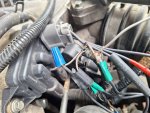
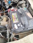
I finally got some wire and connected it from the red/brown wire to the battery negative terminal. See Image.

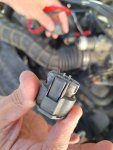
Then with the Key ON, and the connector plugged in I placed the Black probe on the Neg battery terminal and the Red probe on the wire connecting the red/brown wire to the battery terminal.

It bounces but ends on 24.9 and 25.0 mv on Volts DC mv.

I did the same thing with the Light green/brown wire and I got 5.05 and 5.04 Volts, not mV.

I used an old wire not sure if it needs to be a certain gauge or not etc had no automotive wire but will get some if needed...my first try so if I made an error let me know.

Thanks for your patience and assistance in figuring this all out.

SRD
 

Attachments

  • wire from red and brown DPFE wire connected.jpeg
    wire from red and brown DPFE wire connected.jpeg
    202.2 KB · Views: 50
  • wire to neg bettery terminal.jpeg
    wire to neg bettery terminal.jpeg
    165.2 KB · Views: 46
Any wire will work for this testing. I can't see the wire colors in the photos and after a couple days I can't remember which color codes are which because old man memory. :LOL:
Mechrick was suggesting to supply your own ground to the sensor, which I believe was gray/red? So you'd run your wire from there to the battery negative. Then test the signal wire- brown/green was it? test with key on from green/brown to ground. Don't worry too much about which color lead goes where, that's for later electronics lessons. If you have them reversed the meter will read negative volts but it won't hurt anything and the value will be the same, just negative.

edit: FYI, in your first test, you were basically measuring the voltage drop across your improvised ground wire - all wires have a small amount of resistance and therefore the voltage will drop a small amount across a length of wire. These very small fractions of volts can be ignored for these tests. It's that second test that you did that's important- 5 volts is too much there, it needs to be between .5 and 2V
 
Last edited:
So that light green/brown wire should now be reading less than 2 volts. Either the pin of the connector(s) is not making contact with the sensor, or the sensor is bad, or it's wired incorrectly.
 
Hello. Ok, since the issue has been ongoing even before I changed the connector then what would I do to go to the next step?

1. The sensor wire is new and the old one had the same issue.
2. Wires match up correctly color for color so not wired wrong.
3. I have used 4 new DPFE sensors so cannot be that.
4... what's next then?

How would I go about fixing it from here with these readings?

Thanks
SRD
 
Last edited:
I can't find a connector diagram. Someone else want to take a look at their truck? The location of the wires in the connector is what we need.
 
I am not sure if this helps out with what you are looking for. I took a picture of the connector when I changed it so I made sure it was facing the correct position to plug in and I matched wires to color with that so they lined up perfectly and plugged in the same way.

*The connector pigtail might not have been bad if the same issues after replacement. I do make millions of errors so possible I could have done something when installing maybe.

Thanks for the assistance!

SRD
 

Attachments

  • DPFE pigtail.jpeg
    DPFE pigtail.jpeg
    88.9 KB · Views: 49
Well, the connector and pigtail wire looked factory original when I cut them to replace them. The Check Engine Light issues here came on 2 years after I bought the truck so the wire should have been fine until this issue started happening.

*Should I try to swap the end wires to green etc...the center wire stays the same I think. Just an idea as I don't know enough to know really what I am doing just learning what I can.

*Ford dealership even refused to take it in to give me an estimate after I already had made an appointment.....the mechanic said unless all parts were verified Motorcraft he has to pass....really it's old, ugly as all hell and he saw no profit from it I think...lol.

Again, thanks for helping me trench through this problem..its a head-scratcher.

SRD
 
What's going on isn't making sense. The DPFE sensor is a voltage divider. It works like a potentiometer, in that the voltage can vary between the source voltage and source ground. At rest (Key On Engine Off) the sensor output should be less than 2 volts. With all three wires properly connected to the sensor, the ground reference (gray/red) will allow the sensor to pull the output (brown/lt green) down in voltage.

If you lose the ground reference, or the signal wire is open circuit between the sensor and the PCM, the signal voltage will float to 5v because of an internal pull up resistor in the PCM.

The image below shows a voltage divider. If the wiper of the adjustable part is dead center on the resistor, the voltage will be divided by half and the output will be 2.5 volts. If the wiper is closer to ground reference, the output will be closer to 0 volts. Closer to the 5 volt source voltage, the output will be closer to 5 volts.

The DPFE works similarly, in that if connected and Key On Engine Off, voltage output will be a fixed value less than 2 volts.

voltage divider.jpg
 
The reason to check it at the sensor is to verify the integrity of the sensor. If you are truly getting 5 volts on the brown/lt green wire and you are sure the connections are good, then the sensor is bad.
 
Ok, I am trying to digest all of this. I appreciate your educating me; it will take a minute to break it down in my mind and begin to digest it all.

*You are so far beyond me...

*Well, if I got another DPFE and swapped it out again could I test the wires right then to see if the Voltage on the wires has changed at all? If it has NOT changed then I assume it is not the DPFE? and if it has changed then I assume it is fixed and the DPFE was bad?

*Is there a way to test the DPFE by itself? If I can determine the part is good I can assume the wiring is bad...I think?

I repalced a few DPFE so far but never tested them like this...just plugged in and moved on...but I did try 2 Motorcraft and 2 OEM neither seem to fix it but I may not have driven long enough between changes to know?

SRD
 
And do you still have any of those parts you swapped out? I think it would be a good idea to run these same tests with another DPFE plugged in if you have one.
 
Hello. Yes, I do have an OBD2 scanner. but not very capable. What would I need to look for on the reader to run the test you advise? I can check to see if this reader has it.

*Also, I will test all 3 wires again and write it down...then replace DPFE and test all 3 again write it down, and upload the results for review....see if any changes.

*Thanks!

SRD
 
FYI you don't need to go to all the trouble of remounting another module, just plug in the wiring harness and test
 

Sponsored Ad


Sponsored Ad

TRS Events

Member & Vendor Upgrades

For a small yearly donation, you can support this forum and receive a 'Supporting Member' banner, or become a 'Supporting Vendor' and promote your products here. Click the banner to find out how.

Recently Featured

Want to see your truck here? Share your photos and details in the forum.

Ranger Adventure Video

TRS Merchandise

Follow TRS On Instagram

TRS Sponsors


Sponsored Ad


Sponsored Ad


Amazon Deals

Sponsored Ad

Back
Top