Here is the pin out for the EEC-IV:
http://www.auto-diagnostics.info/ford_eec_iv
Pin 53 is the TCC Ground but not shown on this
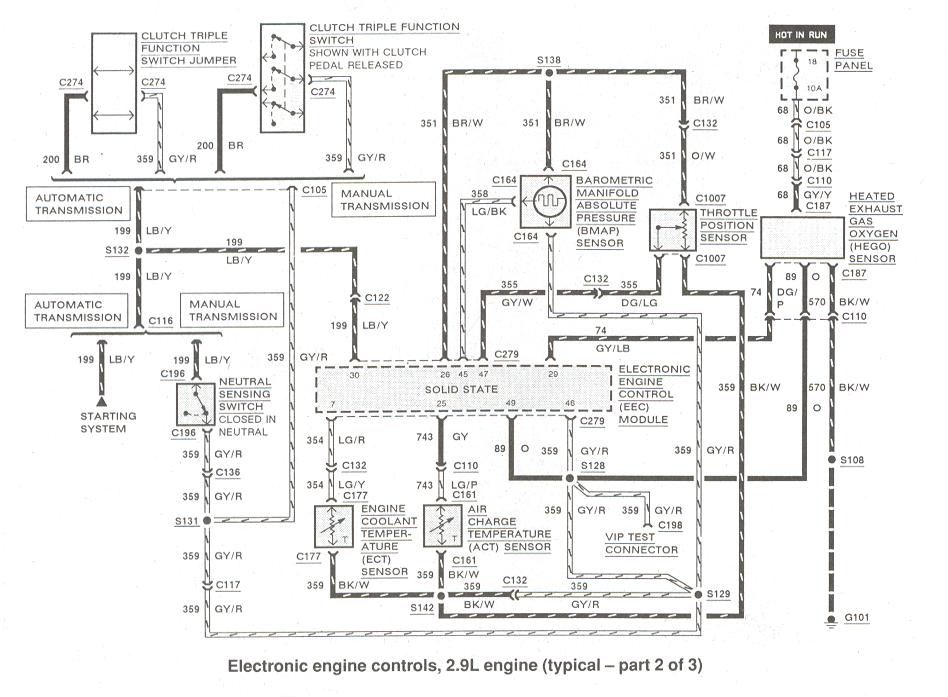
And the electrical diagram of 2.9l:
http://www.therangerstation.com/tech_library/EDiagrams/files/Diagrams_ElectronciEngControls2_9_2of3.JPG
And here, showing TCC at pin 53:
http://www.therangerstation.com/tech_library/EDiagrams/files/Diagrams_ElectronciEngControls2_9_3of3.JPG
TPS and MAP sensor share 5volts from computer, pin 26
Pin 47 is the return voltage you tested.
Pin 46 is the common ground for several sensors, this is a reference ground passing thru the computer so should be tested.
You could test this by using the lower wire on the TPS, the ground from pin 46, and see if voltage on center wire is the same as when testing using an engine ground.
Which reminds me, on the back of the head there should be a Ground strap going to the firewall, this is the main ground for the cab electrics, and is often left off after engine work, make sure that ground strap is there, or add one.
Pin 30 is a trans neutral/in gear sensor, but can't see where it is suppose to get its 5volts from, I assume pin 26 but don't see it in the diagram, so could be incorrect reference.
Is the new computer from an '86?
or could it be from a later model that is looking to control a 2nd trans solenoid?


