
- Joined
- Jun 2, 2012
- Messages
- 25,363
- Reaction score
- 8,371
- Points
- 113
- Location
- canada
- Vehicle Year
- 1994
- Make / Model
- Ford
- Transmission
- Manual
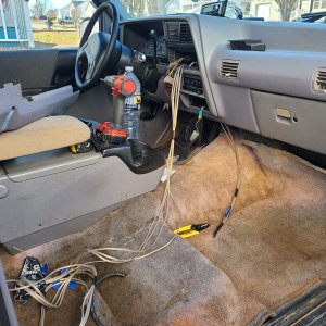
The "S" wire is a W/BLK jumper wire, it needs to be connecting the two "S" connections on the alternator, "S" jumper goes to voltage regulator, so very important to leave this connected, "S" is also AC not DC.Idk maybe if I replace the alt and put the "S" wire back where it belongs and keep the yellow wire on the main post?
It is turned to DC in the regulator and then powers "A" and "I" connections.
The "A" wire, Y/W, supplies power to the Power Distribution box, via a 15A fuse
The "I" wire runs to the "Charge meter" on dash and then to ignition key switch
The "B" wire runs to the Starter relay and then to the Power Distribution box but via a 40 amp fuse.
The "A" wire could be hooked to the "B", they both feed the Power Distribution box, but I would run a new wire.
Best way to test for AC is to disconnect the "B" wire(s) from the alternator.
Cover the wire end, it is still connected to the battery!
Start engine, it is running off the battery now so make the test short.
Set meter for 20vDC, touch black probe to alternator case and red probe to "B" terminal, should have 13.5-14.5vDC
Switch to AC, same test, should be .05 vAC or less
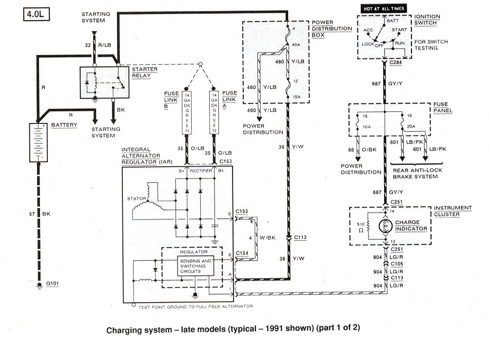
Charging system wiring diagram
http://www.therangerstation.com/tech_library/EDiagrams/files/Diagram_charging_1991_1.JPG
Last edited:


