
Introduction
This modification converts the “switched” oil pressure gauges used by Ford 1987+ to a variable type that moves with oil pressure.
Disclaimer: The Ranger Station.com, The Ranger Station.com Staff, nor the original poster are responsible for you doing this modification to your vehicle. By doing this modification and following this how-to you, the installer, take full responsibility if anything is damaged or messed up. If you have questions, feel free to PM the original poster or ask in the appropriate section of The Ranger Station.com forums.
Tools Needed:
Whatever tools are needed to remove your instrument cluster (1995+ uses 7mm and 8mm sockets/nut drivers)
Soldering iron and supplies (solder, etc.)
Wire stripper/cutter and scrap wire (about 20 gauge will do, stranded preferred).
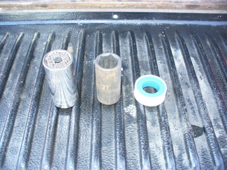
1-1/6″ / 27mm deep socket Socket
9/16″ open ended wrench
“King” 1/2″ drive Gator Grip socket (if using a 45-degree fitting without threads)
Teflon tape/pipe dope (if using a 45-degree fitting)
Socket extensions and a swivel/u-joint adapter (if there are sensor access issues, such as with my 3.0 V6)
Parts Needed
Ford Motorcraft SW-1547-B Oil Pressure Switch. As cheap as these are (I paid around $13 + shipping at Rock Auto in October 2015) I see no reason not to go OE on this. That said, aftermarket ones will (probably) work as well.
EDIT- the one shown actually was faulty out of the box and got worse over time. Wells and Duralast ones are exactly identical to Motorcraft (same manufacturer). BWD one is made by somebody else but so far do just fine.
45-degree 1/4″ NPT Street Elbow. Needed if the sensor is in a tight area. I personally bought a galvanized steel one at Rural King (the only brick and mortar carrier of said fitting); however, these (both galvanized and brass) can be ordered elsewhere, such as here. If you have the choice, get one with wrench flats; however, round ones will also work (as I did, see below).

Step 1: Verify that this modification is possible. Remove your instrument cluster. For 1995 and later, this guide has good instructions. I haven’t personally worked on pre-1995 rangers, although the process is probably similar. Once the cluster is out, look on the back of the cluster, near the oil pressure gauge for a 20 ohm (Ω) resistor (color code red black black); on many vehicles this will be marked “20 Ω”. If such a resistor is not found (possible on later models), then this modification isn’t possible; re-install your cluster and follow this guide to add a separate oil pressure gauge. If you found that resistor, then continue on…
Step 2: Solder a jumper wire across the 20Ω resistor, like so (the pictures are from my 1995 Ranger 3.0):

What we are doing is removing the resistor from the circuit. The way oil pressure gauges work is through current flowing through a coil in the gauge’s needle. The existing setup used a switch at the engine (which will be swapped out in the next step) and this resistor to regulate the current flowing though the gauge. The way the pre-1987 gauges (and what we are converting to) works is through a variable resistance sensor; since the current regulation is done through the gauge itself, the existing resistor is redundant and will over-regulate the current (resulting in a gauge that will barely rise above “L”). Shorting out the resistor re-directs the current around the resistor, allowing the current to be solely regulated by the sensor.
Step 3: Re-install the instrument cluster. Do not start the engine, for the sake of the presently de-regulated pressure gauge. If you need to (emergency comes up, etc.), unplug the sensor at engine (see below)
Step 4: Open your hood and locate the oil pressure sensor. On the Vulcan 3.0, it will be located behind the cylinder head on the passenger’s side. It may help to remove some of the wiring in the vicinity (IIRC I unplugged the O2 sensor, disconnected the ECU harness, and removed the cable restraint/ground for said harness). Either way, the existing switch will look like this:

Step 5: Disconnect the push-on connector from the sensor. Remove the sensor with a 1-1/16″ or 27mm socket. In my case, there was a clearance issue with the automatic transmission fill tube; while the “ideal” solution is to remove the anchoring bellhousing bolt and remove the tube (which isn’t a bad idea, more work space), due to the bold being difficult to get to and remove with the tools on hand, I just nudged (bent) the tube back a bit. Maybe a few millimeters if anything. As long as the tube isn’t kinked, it will still read the fill level correctly as the tube is still the same length.
Step 6a: If a 45-degree fitting is needed for clearance issues, apply a small amount of Teflon tape/pipe dope to the male end. The tape is there to reduce friction, not to seal (as the tapered threads tightening creates the seal. Likewise, the threads will cut through the tape at the thread’s edges, which will provide the necessary ground connection to the engine block.
Step 6b: Install the 45-degree fitting. If you have a round (no flats) fitting like I did, the only way the turn it tight (with the engine installed) is to use a 1/2″ drive “king” gator grip socket. Press the socket on the fitting and wrench on it. The socket will want to tilt towards the female end of the fitting; use one hand to turn your ratchet while using the other to brace the socket. Turn until reasonably tight, with the fitting pointing towards an empty space big enough for the sensor and near the wiring loom with the sensor connection.
Step 7: Install the new sensor with a 9/16″ open ended wrench. The Ford Motorcraft sensors come with Teflon pre-applied; additional Teflon is not needed. Connect the push-on connector to the new sensor; with some re-location of the wiring harness the cable should reach. Once installed, in my case, the sensor + 45-degree fitting looked like this:

Step 8: Replace any wiring or the like that was removed to gain access to the sensor. Start the engine and verify that the gauge is reading plausibly. Check the sensor area for oil leaks. Hopefully your engine is healthy, and you observe good pressure. If not, well… your engine may have seen better days (or the jumper wire isn’t soldered correctly to the right places). In my case I had a bouncy needle; I later (during a partial engine teardown out of the truck) found evidence that a previous owner didn’t like to change their oil which may be to blame. I have also heard that since these gauges were designed for switches, they may be a little twitchier than a gauge designed for a variable sender.
EDIT- anything more than a tiny twitch (barely noticeable) is NOT normal and indicates a faulty sensor. If this happens, either swap the sensor or verify with a mechanical gauge.
Step 9: Enjoy having an oil pressure gauge that actually works as a gauge. If you ever give/sell the truck away, be sure to have this modification noted somewhere, for the sake of the next owner.
Update
One Year later after the mod, I’ve discovered some things:
Apparently the Duralast brand oil pressure sensors are made by Wells, who also makes Motorcraft sensors, to the point of the Duralast one having the same marks (and ford stamp) as Motorcraft.
BWD sensors are a different manufacturer but work fine as well.
I know those because my readings were getting worse and worse (lower and bouncier) but a mechanical pressure gauge revealed that the sending unit had been wrong this entire time. I put in a new sending unit, and that fixed it. I would have gone with the Duralast sending unit had the local Autozone’s internet not been out (cash only). Instead, I popped over to Advance Auto Parts and grabbed a BWD one there… which revealed much better-looking oil pressure readings. Lesson learned: even OE parts can be faulty out of the box… Hence why I’m going to edit my original submission to reflect such.
Links
View the original forum submission HERE.
Contributor
This modification was performed and documented by TRS forum member Larry Bolan (ratdude747) and submitted to the author to publish at The Ranger Station to help other Ford Ranger owners.
Related Article
Aftermarket, piggy back, oil sender installation
Last Updated:
About The Author
Jim Oaks is the founder of TheRangerStation.com, the longest-running Ford Ranger resource online since 1999. With over 25 years of hands-on experience building and modifying Ford Rangers — including magazine-featured builds like Project Transformer — Jim has become one of the most trusted authorities in the Ford Ranger off-road and enthusiast space.
Since launching TheRangerStation.com, Jim has documented thousands of real-world Ranger builds, technical repairs, drivetrain swaps, suspension modifications, and off-road adventures contributed by owners worldwide. TheRangerStation.com has been referenced in print, video and online by enthusiasts, mechanics, and off-road builders looking for practical, and experience-based information.