
Introduction
Whenever wiring off road lights or accessories, it’s important to know how many Amps the lights or accessory are using and use a relay when necessary. This article explains what a relay is and when to use it. For the purpose of this article, I’m just going to make reference to ‘light’ so I’m not constantly typing ‘lights or accessory’.
What is a 12V Relay?
With a relay, when a switch is turned on and sends 12-volts to a relay, the relay is then ‘turned on’ and connects 12-volts from a fused battery connection straight to the light without having to travel all the way to the switch and then to the light. Think of a relay as an electronic switch rated to handle more power than a standard 12-volt switch.
A more technical explanation would be: A 12V relay is an electrically operated switch that allows a low-power signal to control a high-power circuit. It consists of two main parts: an input circuit with an electromagnet (coil) and an output circuit with switch contacts. When a 12V current flows through the coil, it creates a magnetic field that moves an armature, opening or closing the contacts to control the flow of electricity to connected devices.
Most relays are rated at 30 or 40 Amps. Make sure you use a relay rated for the number of Amps you’re using.
Key Benefits of Using a 12V Relay
Power Control: Relays enable you to switch high-current devices (like lights, motors, or compressors) using low-current switches. This means you can use a small switch to control larger loads without risking damage to the switch itself.
System Protection: By keeping high currents away from dashboard switches and control panels, relays reduce the risk of overheating and electrical fires. They also allow for cleaner wiring systems, especially in vehicles with multiple aftermarket accessories.
Efficiency: Using relays minimizes voltage drop between the battery and the device, ensuring that the connected devices operate at peak performance levels. This is particularly important in automotive applications where maintaining voltage is crucial.
Convenience: Relays allow for the control of multiple devices with a single switch, simplifying the wiring and making it easier to manage electrical systems. This is especially useful in race cars or custom builds where space and weight are considerations.
Versatility: 12V relays are widely used in various applications, including automotive lighting, horns, winches, and other high-raw accessories. They are a standard component in many electrical systems due to their reliability and effectiveness.
When Do You Need a Relay?
A relay is necessary when the light draws high current (Amps) that exceeds the capacity of the switch or wiring, ensuring safe operation. If you’re using a low-power switch, which is common in many dashboard switches, it may not be designed to handle high current loads directly. A relay can also help avoid voltage drop by providing a shorter, more direct connection to the battery, minimizing power loss. Additionally, when controlling multiple high-power lights, a relay simplifies the wiring process, making it easier and safer to manage the electrical load.
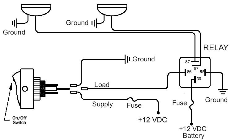
How To Wire A SPST Relay
As mentioned above, sometimes a wiring harness might use a SPST relay, or you may want to use a relay with a terminal connection to each light. The diagram below shows how to wire a SPST relay. Notice that instead of an 87a terminal, there are now (2) 87 terminals.

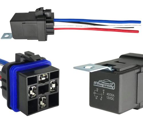
How To Tell SPDT And SPST Relays Apart
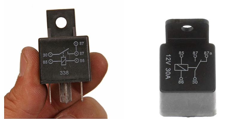
If you’re not sure if you’re getting the right relay, the relay will have its connections diagram printed on the casing. You can see in the photo below that the relay on the left is a SPST with (2) 87 terminals and the one on the right is a SPDT with an 87 and 87a terminal.
What Does All Of This SPDT and SPST Even Stand For?
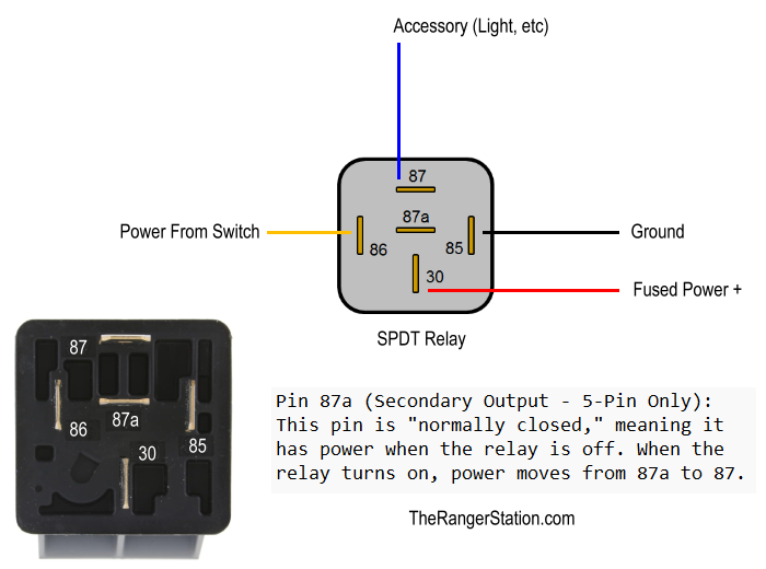
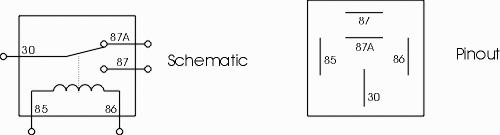
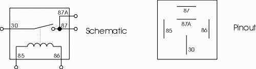
SPDT Relay (Single Pole Double Throw Relay): an electromagnetic switch, consist of a coil (terminals 85 & 86), 1 common terminal (30), 1 normally closed terminal (87a), and one normally open terminal (87).
When the coil of the relay is at rest (not energized), the common terminal (30) and the normally closed terminal (87a) have continuity. When the coil is energized, the common terminal (30) and the normally open terminal (87) have continuity.
This relay is similar to a SPST, but pin 30 is switched to either output pin 87A or pin 87. Pin 87A is connected in the unpowered state.
SPST Relay (Single Pole Single Throw Relay): an electromagnetic switch, consist of a coil (terminals 85 & 86), 1 common terminal (30), and one normally open terminal (87). It does not have a normally closed terminal like the SPDT relay but may be used in place of SPDT relays in all diagrams shown on this site where terminal 87a is not used.
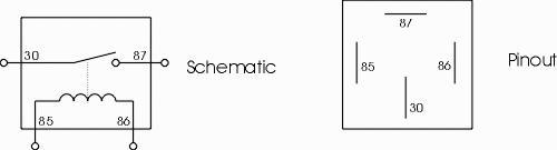
When +12V is applied between pins 85 and 86 the coil becomes a magnet which pulls the lever down making a connection between pins 30 and 87.
The relay above is a SPST relay with dual outputs. These are getting harder to find. If you find one, it’s usually from a company that sells offroad lighting such as:
KC HiLiTES 3300 40 Amp Relay
Wiring Diagram Examples
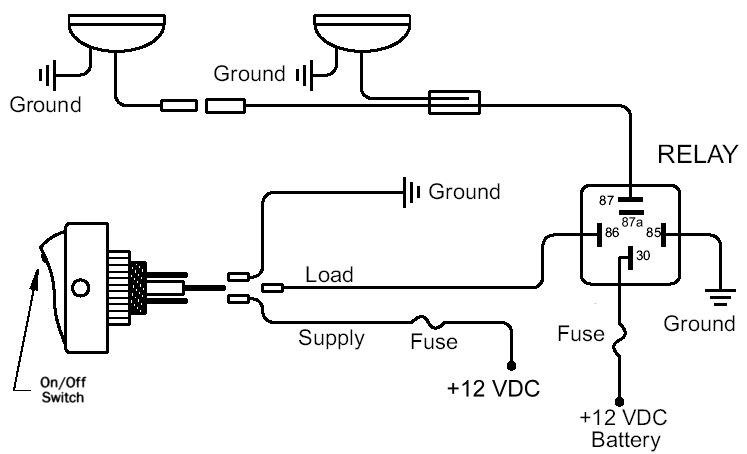
SPDT Above / SPST Below
Buy Or Build Your Own Harness
If you bought some off-road lights that didn’t come with a harness you can either;
Make your own harness using a 12V relay and attach the wires to the relay terminals with female connectors
Buy a relay with a wired waterproof housing and build from there
Buy a complete 12V Wiring Harness that comes with a switch and relay (probably costs the same as building your own). These come with a single lead and dual lead for a single or dual light setup, so make sure you buy the right one.
Choosing The Right Wire Gauge
The first thing you have to do is determine the number of Amps the wire has to carry. Auxiliary fans, fuel pumps and things like that are rated in current draw – Amps. Some equipment is rated in Watts – mostly the lighting equipment. The power requirement in Watts will be printed right on the bulb or stamped in the base. If you bought it knew than it should be on the packaging. To come up with Amps use one of the formulas shown.
- Amps = Watts / Volts
- Amps = Volts / Resistance (Ohms)
- Amps = Square Root of (Watts/Ohms)
- Watts = Amps x Volts
- Volts = Watts / Amps
Let’s calculate for a typical 100 watt driving light:
The power required is 100 Watts and the voltage is 12 Volts – so the Amps would be 100 Watts / 12 Volts = 8.33 Amps. If you were using (2) 100-watt lights, then you would be drawing 16.66 Amps (8.33 + 8.33).
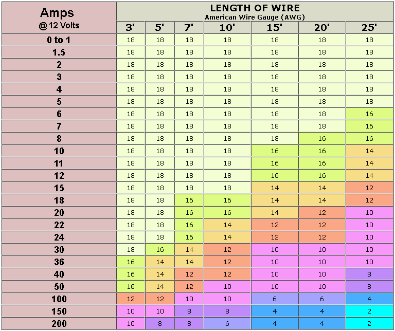
Let’s assume you have to run a wire 8 feet from a relay to the lamp (or 6 feet from the battery to the relay) and look at the chart below. The number along the left indicates the Amps, the columns to the right are divided into feet, and then the number inside of those boxes represents wire gauge (AWG).
As you can see from the chart, going down to 8 Amps, we can follow that all the way over to 15 feet using 18-gauge wire (I personally never use anything smaller than 16-gauge). But if we’re powering (2) lights at 16.66 Amps, we would have to use 16-gauge wire.
A pair of round LED offroad lights rated at 140-watts each would be 23.22 Amps (140 x 2 = 280. 280 / 12 = 23.22). Using the chart, we’ll have to round up to 24 Amps and using the chart I would need a 14-gauge wire.
Summary
A 12V relay is a crucial component in modern electrical systems, particularly in automotive and industrial applications. It enhances safety, efficiency, and convenience by allowing low-power switches to control high-power devices, protecting the overall system from overloads and ensuring optimal performance.
Related Article
Selecting The Proper Wire Size
Last Updated:
About The Author
Jim Oaks is the founder of TheRangerStation.com, the longest-running Ford Ranger resource online since 1999. With over 25 years of hands-on experience building and modifying Ford Rangers — including magazine-featured builds like Project Transformer — Jim has become one of the most trusted authorities in the Ford Ranger off-road and enthusiast space.
Since launching TheRangerStation.com, Jim has documented thousands of real-world Ranger builds, technical repairs, drivetrain swaps, suspension modifications, and off-road adventures contributed by owners worldwide. TheRangerStation.com has been referenced in print, video and online by enthusiasts, mechanics, and off-road builders looking for practical, and experience-based information.