• Welcome Visitor! Please take a few seconds and Register for our forum. Even if you don't want to post, you can still 'Like' and react to posts.

IAC Wiring


JerrySab

Well-Known Member
Joined
Jul 11, 2020
Messages
217
Age
44
City
Los Angeles
Vehicle Year
1988
Engine
2.9 V6
Transmission
Automatic
Hey gang!
This may belong in electrical, but starting here as it may be engine specific.

I’m taking the opportunity to comb through the wiring while the engine is still out, and found the ground wire for my Idle control valve to have 1.3-6 ohms from pigtail to connector.

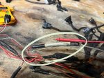
which is kind of a smoking gun to me, but wanted to confirm that there isn’t a resistor in this rubber sleeve.

also, what is this sleeve? Is it like an inline fuse?

thanks
 

Attachments

  • IMG_1993.jpeg
    IMG_1993.jpeg
    224.6 KB · Views: 137
The '88 schematics do show a diode in the circuit, but the drawing shows the reverse of what you've pictured.

Wouldn't be the first typo I've seen in the Ford schematics, and it should be easy to confirm/check with your meter.

Basically it looks like they've put a quenching diode across the solenoid coil.

88 engine control 29 b.JPG
 
The IAC is nothing more than a coil of wire, solenoid. Whenever you energize a coil of wire and then turn it off, you get a kickback in the voltage. The diode is there to allow the voltage to continue flowing around the circuit until it dissipates when the power is turned off.

A diode does have a small amount of resistance. I would reverse your meter leads and just ensure that there is zero continuity the other direction.

I was looking for a Motorcraft IAC replacement for my 86... which I could find zero. In later models (I thought it was 88 MY) Ford removed the diode from the harness an incorporated it into the IAC itself. These updated IAC's can be used on older harnesses with a diode with no ill effects. Reversing the wires in the IAC connector might be necessary if the new IAC doesn't work. This was all put into a service bulletin from Ford.
 
Last edited:
Thank you both for the very clear explanations on the diode. I was just able to check for continuity from both directions, and found resistance going both ways.

Connector > pigtail - 2.3 ohms
Pigtail > connector - 1.6

BUT. Knowing there’s a diode in the IAC itself, I’m strongly considering snipping the wired diode out.

ALSO also, is there such thing as a negligible amount of resistance? My understanding was 00.0 or bust. If a wire is showing 00.1 ohms, does it need to be replaced?
 
A wire will have some resistance related to the length of the run. Rather than splitting ohms and reading tea leaves or chicken guts, I'd rather just test for any voltage drop at the IAC compared to battery voltage to check if the circuit is good or not.

Based on @Uncle Gump 's experience I'd say that you're OK to try running it with the diode snipped out and bypassed.
 
Thank you both for the very clear explanations on the diode. I was just able to check for continuity from both directions, and found resistance going both ways.

Connector > pigtail - 2.3 ohms
Pigtail > connector - 1.6

BUT. Knowing there’s a diode in the IAC itself, I’m strongly considering snipping the wired diode out.

ALSO also, is there such thing as a negligible amount of resistance? My understanding was 00.0 or bust. If a wire is showing 00.1 ohms, does it need to be replaced?
Resistance readings that low may vary by the quality (cleanliness and tightness) of the connection with your meter leads, quality of the meter, freshness of the meter’s battery and more. Plus, as mentioned the wire does have resistance that will vary by wire size and length.
 
Thank you both for the very clear explanations on the diode. I was just able to check for continuity from both directions, and found resistance going both ways.

Connector > pigtail - 2.3 ohms
Pigtail > connector - 1.6

BUT. Knowing there’s a diode in the IAC itself, I’m strongly considering snipping the wired diode out.

ALSO also, is there such thing as a negligible amount of resistance? My understanding was 00.0 or bust. If a wire is showing 00.1 ohms, does it need to be replaced?
Like was said, you will get that sometimes by just holding the meter leads together.
 
To make clear about the diode in later model IAC solenoids...

If the IAC has an internal diode... the diode symbol will be cast into the IAC connector housing... as shown below.

Screenshot_20240110_074416_Google.jpg
 
The IAC's Ground wire is the Control wire that runs to pin 21 on the PCM(ECM)
So its not a direct ground to battery negative
Ford uses a PWM(pulse width modulation) circuit in the PCM to control IAC Valve, and that's the circuit you are reading OHMs thru

Can't say what would be correct OHMs key off, but for sure not 0 ohms, as its not a direct ground
 
I assumed... bad idea I know

Your resistance test should have been done with that circuit isolated. Meaning harness disconnected on BOTH ends... and reading resistance on that circuit and not to ground.
 
@Uncle Gump @RonD

Your assumption is correct! Harness is disconnected. Not measuring plug to negative terminal or chassis ground. I'm measuring resistance across the diode, but it's just easier to measure from the pins on the disconnected harness.
 
Your resistance test should have been done with that circuit isolated. Meaning harness disconnected on BOTH ends... and reading resistance on that circuit and not to ground.

Harness is disconnected. Not measuring plug to negative terminal or chassis ground. I'm measuring resistance across the diode, but it's just easier to measure from the pins on the disconnected harness.

Yes, to test the ohm resistance of the complete IAC control circuit you do need to disconnect both connectors, IAC and PCM, and probe the terminals with the meter on both ends. With the harness out and on the bench that would be OK, but it's very difficult to do such a test accurately with the harness in place in the vehicle.

On the other hand, it would be relatively easy to just replace the blown diode, as it did fail in your testing, and then see how the truck does from there.
 
Great. Appreciate all of the wisdom, fellas.

If the diode is in fact cooked, would there be any other relays that would merit inspection? Not sure how it died, but if it was from excessive current or reverse voltage, would there be anything else on that circuit that could fry? Other than PCM? Looking through wiring diagrams, that Red 361 wire seems to touch a lot of stuff.
 
Last edited:
A voltage drop test on the Red 361 wire at the IAC, after replacing the diode, would the easiest way to tell if there's anything else that needs to be looked at on the power side.
 

Sponsored Ad


Sponsored Ad

Overland of America

TRS Events

Member & Vendor Upgrades

For a small yearly donation, you can support this forum and receive a 'Supporting Member' banner, or become a 'Supporting Vendor' and promote your products here. Click the banner to find out how.

Recently Featured

Want to see your truck here? Share your photos and details in the forum.

Our Latest Video

TRS Merchandise

Follow TRS On Instagram

TRS Sponsors


Sponsored Ad


Sponsored Ad


Amazon Deals

Sponsored Ad

Back
Top