Rick W’s first gen Ranger alternator replacement/upgrade


Rick W

Lil Big Rig

⭐Supporting Member
TRS Event Participant
TRS 25th Anniversary
Truck of Month
Joined
May 15, 2020
Messages
5,099
Points
601
Age
71
City
Atlanta
State - Country
GA - USA
Other
Manufacturers factory tour, maybe big dealership tour
Vehicle Year
1997 1987
Vehicle
Ford Ranger
Engine
4.0 V6
Transmission
Manual
Total Lift
97 stock, 3” on 87
Total Drop
N/A
Tire Size
235/75-15
My credo
Never put off ‘til tomorrow what you can put off indefinitely
HELP!!!

I hooked up the new alternator, the way it showed all over the Internet, and I burned up a wire in my main wiring harness. Frustrated, not happy

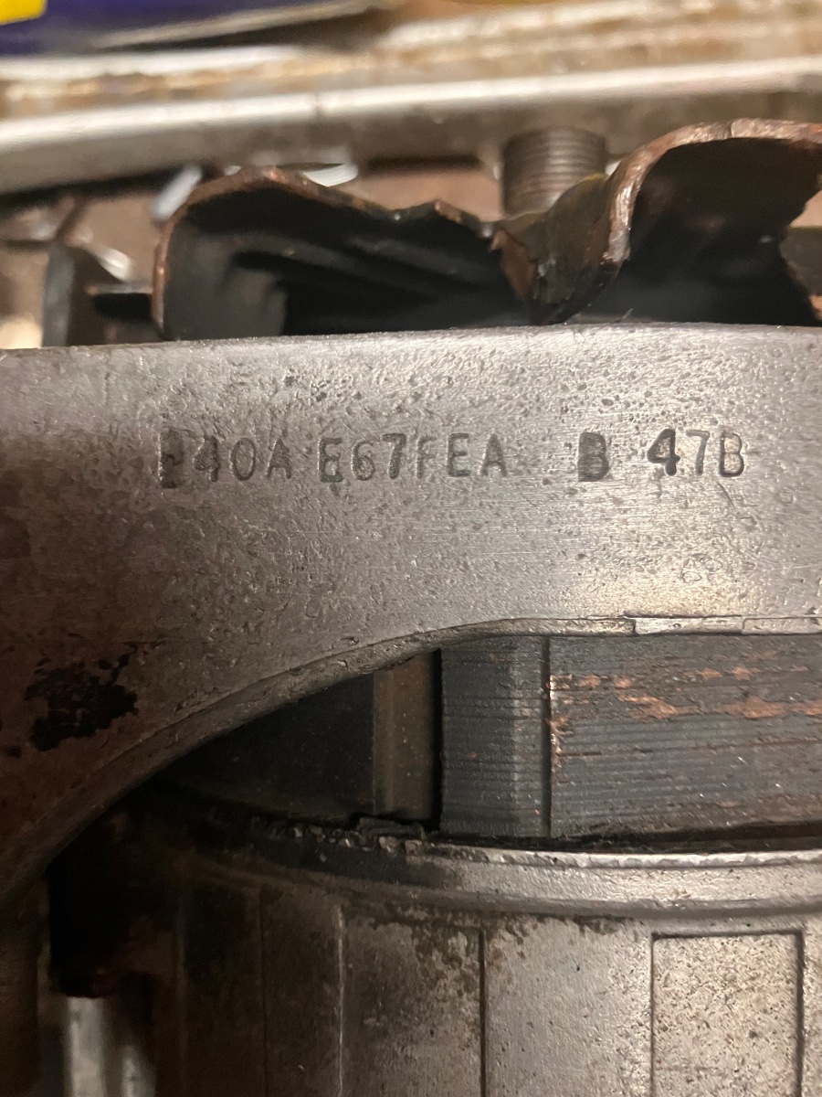
1987 Ranger 2.9. Original I think if I had known it was 40 A, I would’ve just gotten a couple AA batteries to replace it. This stamped number was on the bottom side, so there was no way to see it without taking the alternator off. I was assuming it was a 60 or 65A since that all it says in the literature. I bought an 80 amp replacement.

slternator:
Rick W’s first gen Ranger alternator replacement/upgrade


OLD 40A & truck wires: It has a 3-prong “D” connector on the top, but only two wires: a skinny green wire and a heavier yellow wire. On the bottom side, the main power wires were made right into the alternator (no connector) with a 3 foot lead that went over by the firewall in front of the driver. The original had two black wires that connected together about 8 inches from the alternator.

That skinny green wire, wider yellow wire, and the heavy black wire go across the engine to a 3-prong connector that goes into the wiring harness under the dashboard. On the dashboard side, the yellow is yellow, the black is black, but the green transitions to a green with a red stripe on the truck side of the connector.

NEW 80A: The new alternator has the female for the D connector. On the bottom, there are two heavy black wires, and a white wire. From reading everything and talking to you guys, the two black wires get connected into one as before. The white wire is the stater/exciter wire, and everything says to connect a power source that only comes on with the ignition, but nothing specifies a good place to do that

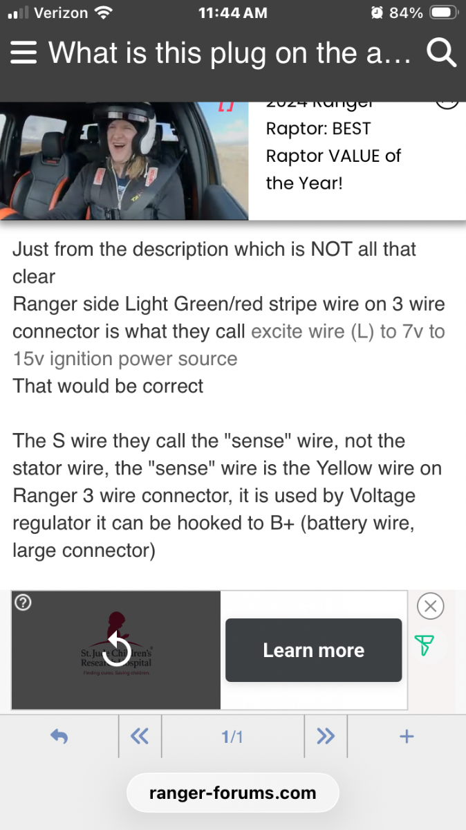
In several places, the literature says that that white wire can be connected to the green wire with red stripe, which is the same green wire that comes out of the top of the alternator
Rick W’s first gen Ranger alternator replacement/upgrade


So that’s what I did. Two black into one black that stays black after the three prong connector by the firewall. Yellow stays yellow through that connector. The green wire turns into a green wire with red stripe after that connector. So I connected the exciter/stater wire on the new alternator to the green wire coming from the alternator.

I turned it off when the smoke started pouring from underneath the dashboard then some accessories went dark. It burned up the green wire with the red stripe from under the hood to under the dash.

So, two questions. Where does that green wire with the red stripe go under the dash? Does it just go to the fuse panel or does it go up to the ignition switch or what? I obviously have to replace that wire.

And where in the holy heck should I connect that white wire? Please don’t tell me a source powered by the ignition, please tell me specifically what wire under the hood by the brake booster I should tie into.
Rick W’s first gen Ranger alternator replacement/upgrade


Did I say. HELP!
 
I wish I understood your description better. Maybe pictures would help?

I'm getting the impression that you had an old externally regulated alternator before and put an internally regulated one on?

I did some more wiring cleanup myself. I hope I haven't broken anything. There is a connector in the drivers fender/firewall area for the speed sensor, and a perfectly matching connector that has 2 similarly colored wires for some interior lights. They were plugged together. I'm hoping non of that ended up tied into the computer. (Good thing I have a spare.) While tracking all that down, I found out that 88 wiring colors are more of a suggestion at this point. VSS has a dark green/white wire and the tach signal is dark green/yellow. About an inch apart. Thanks Ford. :annoyed:

It's all correct now. PCM only complains off fuel pump circuit failure (I forgot to plug it back in at first.) and code 173 while running. It can't seem to make up it's mind if it's lean or rich. Got 173 today and 172 yesterday. Now to see how it drives a few days.
 
Last edited:
I wish I understood your description better. Maybe pictures would help?

I'm getting the impression that you had an old externally regulated alternator before and put an internally regulated one on?

I did some more wiring cleanup myself. I hope I haven't broken anything. There is a connector in the drivers fender/firewall area for the speed sensor, and a perfectly matching connector that has 2 similarly colored wires for some interior lights. They were plugged together. I'm hoping non of that ended up tied into the computer. (Good thing I have a spare.) While tracking all that down, I found out that 88 wiring colors are more of a suggestion at this point. VSS has a dark green/white wire and the tach signal is dark green/yellow. About an inch apart. Thanks Ford. :annoyed:

It's all correct now. PCM only complains off fuel pump circuit failure (I forgot to plug it back in at first.) and code 173 while running. It can't seem to make up it's mind if it's lean or rich. Got 173 today and 172 yesterday. Now to see how it drives a few days.

Old alternator and new alternator, both have internal voltage regulator. Physically, they’re almost identical.
 
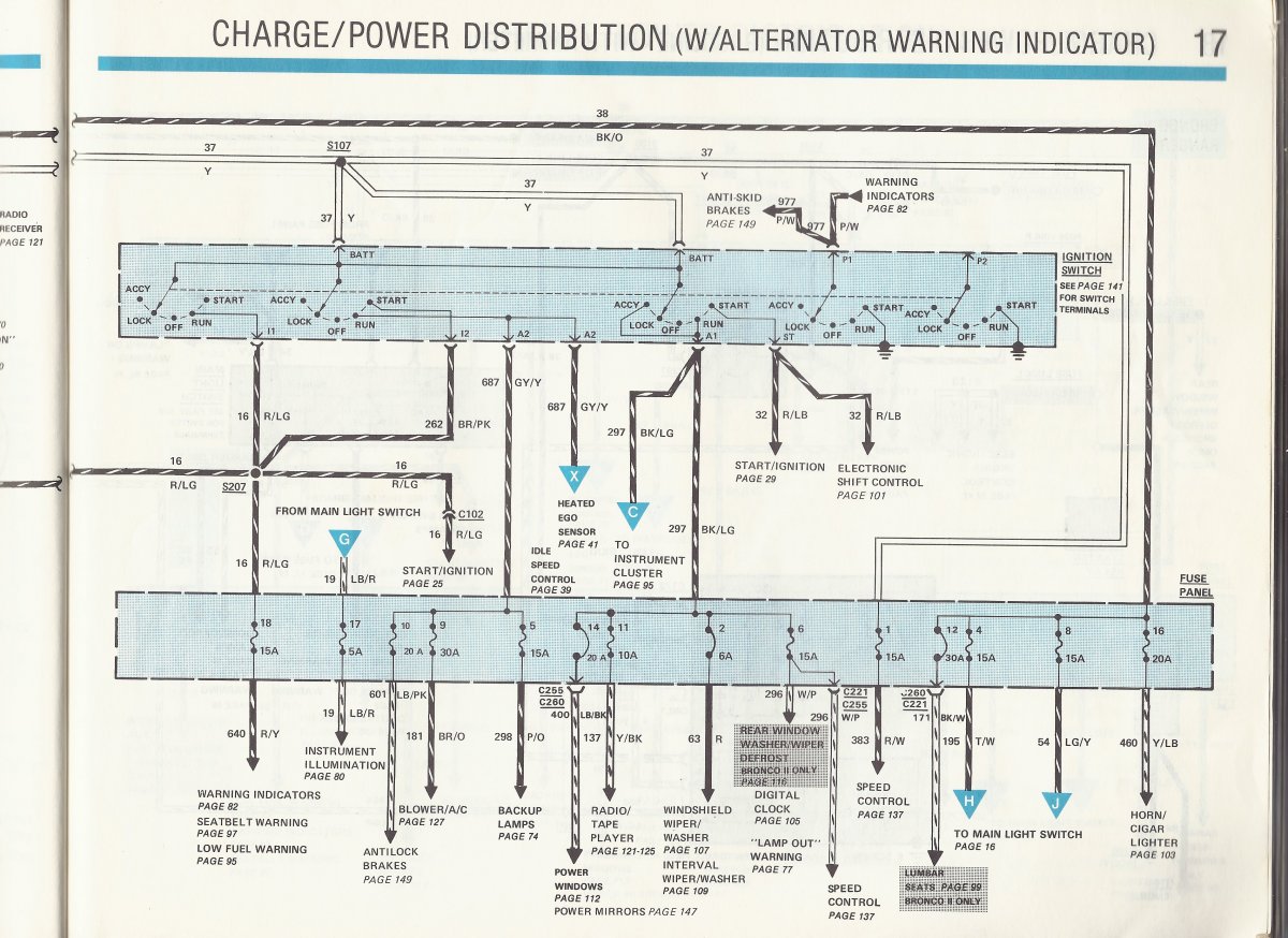
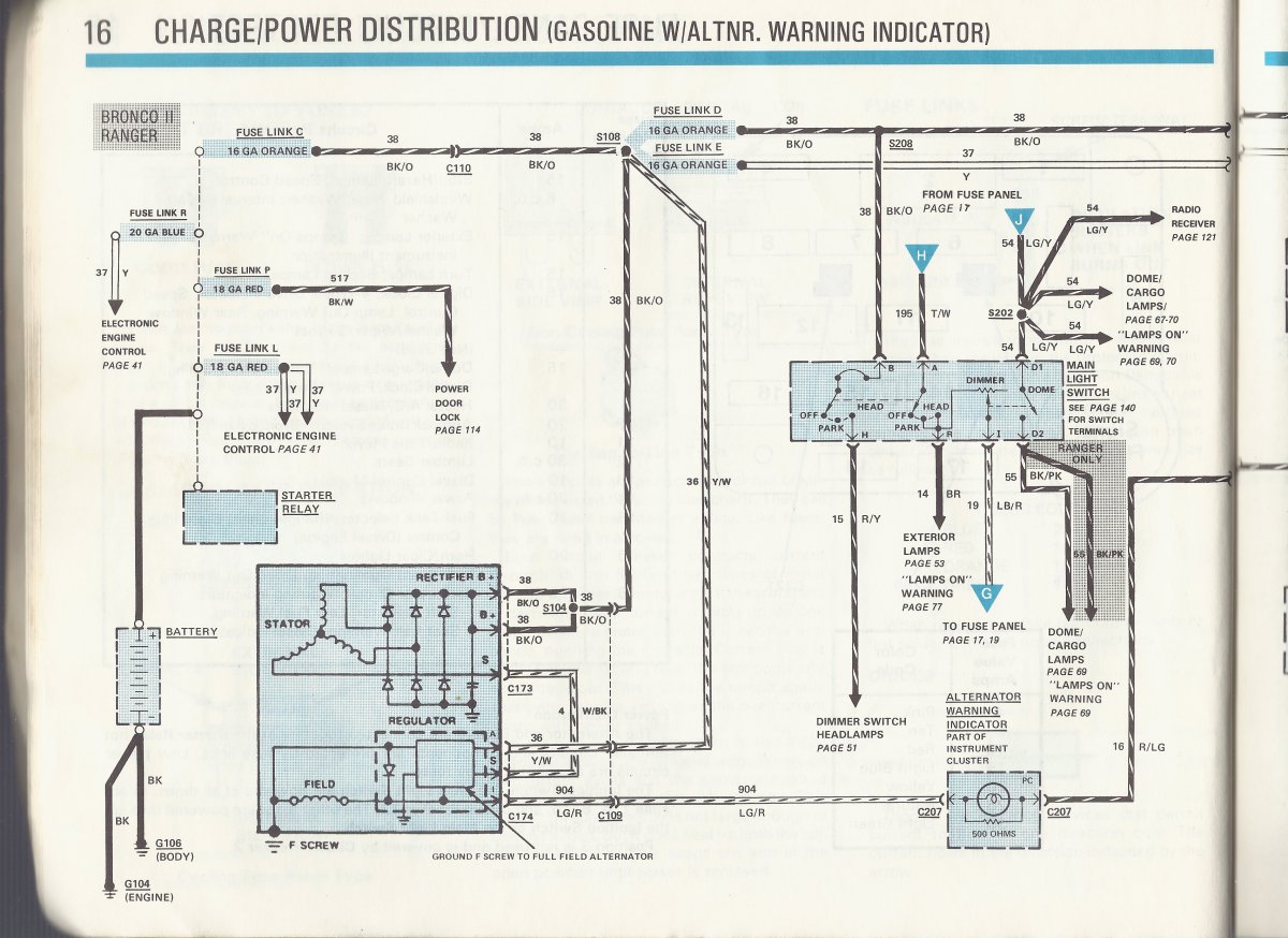
The wire colors you are stating don't make sense with the diagrams. The Light Green wire with red stripe comes from the battery charge indicator lamp in the gauge cluster. It should not be connected to anythung else. That 12v circuit comes from the ignition switch.

Here's part of the diagram. I'll post the other page in a minute.


Amen to no sense, but just fyi, when they tell you how to put in the upgraded alternator, they say to attach that white ignite wire to the battery idiot lamp. The concept is that when you turn the ignition switch on, it gives power to that lamp, which lets the alternator ignite, and then the light goes out, and therefore cuts the power on that line to the alternator. I don’t think I even have an idiot light for the alternator in this truck, it just has the gauge. In that clip I posted above, it specifically says the green wire with the red stripe…

More info:

IMG_7924.jpeg


Above is the way it was before I touched it. Below is the new alternator. Everything is the same, except you have the one extra white wire coming from the bigger bottom connector. When I connected that to the Green, which across the connect becomes the green with red stripe, it burned that wire to a crisp.

New alternator connector with the extra white wire, the ignite wire:
IMG_7927.jpeg


“D” connector on the top of the alternator. It is a three pin connector, but one of them is not connected and it’s just plugged:
IMG_7930.jpeg
IMG_7932.jpeg


And here is the three pin connector that is over underneath the brake booster. The green wire from the top of the alternator goes through that three pin connector into the green with red stripe wire. You can see where that wire is burned up:
IMG_7934.jpeg


First question, to repair the burned up wire, does anybody know how that is routed up to the ignition switch? Does it just go from this plug to that switch, or is there a branch off somewhere? I’m just about to pull the column apart to try to chase it down. May plan is to just cut the old wire at both ends and run a new wire outside the harness. I already stripped down the harness from the alternator to the connector under the brake booster and replaced the wire there.

Second question, the original question, what should I connect that white wire to that’s around the brake booster? I’m looking for something I can see, not the wiring diagram*, if possible. Otherwise I’ll just find something in the fuse panel that becomes hot when you turn on the key.

* and I do appreciate the diagrams and the help.
 
I'll look at this more in-depth later, after dinner. In the mean time, here is a description of how the wiring for the charge indicator works. "I" is not "ignitor". And, if I may make one more request on behalf of good communications and everyone's sanity. Please refer to each wire by it's full color name. If it is black with an orange stripe, please do not merely call it black. Some wires just have one color, such as yellow, and some have a primary color and a marker (usually a stripe or dashed stripe). These are referred to by their primary color first and the marker second, such as yellow/white or "Y/W" or DG/LG for Dark Green with light green stripe. Using this standard makes a huge difference in making sure everyone understands which wire you are talking about.

20260728_170656.jpg


Trust me. Those dang stripes matter.
20260728_165638.jpg
20260727_144959.jpg
 
Are there any raised or stamped letters on the alternator case near each terminal?
 
I'll look at this more in-depth later, after dinner. In the mean time, here is a description of how the wiring for the charge indicator works. "I" is not "ignitor". And, if I may make one more request on behalf of good communications and everyone's sanity. Please refer to each wire by it's full color name. If it is black with an orange stripe, please do not merely call it black. Some wires just have one color, such as yellow, and some have a primary color and a marker (usually a stripe or dashed stripe). These are referred to by their primary color first and the marker second, such as yellow/white or "Y/W" or DG/LG for Dark Green with light green stripe. Using this standard makes a huge difference in making sure everyone understands which wire you are talking about.

View attachment 146645

Trust me. Those dang stripes matter.
View attachment 146646View attachment 146647

Understood, good advice and direction for TRS and all of us. I’m frustrated, but I appreciate everything you do, and I agree with what you’re saying.

More clarification on my wire colors…

On the new alternator, the bottom plug with the heavy duty wires are two heavy black with a red stripe, and the white wire that has a thin black stripe. However, there is no confusion that those two black red wires are in the place of the two similar size solid black wires from the old alternator.

The new additional wire, the white wire with the little black stripe, is described in the instructions and all over the Internet as the stater/exciter wire. There’s also no confusion that that is supposed to connect to a circuit that only becomes hot when you turn on the ignition, but there is no further suggestion on which circuit you should connect to. Apparently that stater/exciter wire needs voltage from the ignition switch to start the voltage regulator, but it doesn’t have to maintain current after that. The Internet and literature all say to connected to the trouble light bulb for the battery if you’ve got one.

The bed information I got was that the green wire from the top of the alternator which transitions to a green wire with red stripe at the connector by the brake booster was the place to connect that wire. When I did that, the green wire with the red stripe fried, as well as the line I had run to the white wire with black stripe the 3 feet across the engine.

Update, I fixed the harness from the alternator to the connector by the brake booster. I got upside down and backwards and took out half the dashboard, and I found where the green wire with the red stripe was fried. I’m still not sure where it goes up towards the steering column, but it was only burned for about 12 inches, 6 inches inside the fire wall and 6 inches outside the firewall. A couple other wires got a little scorched, but nothing seems to be damaged. I have yet to put it back together.

So I’m still hunting for an easy place to tie in that stater/exciter wire…

@Curious Hound , you keep on riding me, it keeps me energized!
 
I'll look at this more in-depth later, after dinner. In the mean time, here is a description of how the wiring for the charge indicator works. "I" is not "ignitor". And, if I may make one more request on behalf of good communications and everyone's sanity. Please refer to each wire by it's full color name. If it is black with an orange stripe, please do not merely call it black. Some wires just have one color, such as yellow, and some have a primary color and a marker (usually a stripe or dashed stripe). These are referred to by their primary color first and the marker second, such as yellow/white or "Y/W" or DG/LG for Dark Green with light green stripe. Using this standard makes a huge difference in making sure everyone understands which wire you are talking about.

View attachment 146645

Trust me. Those dang stripes matter.
View attachment 146646View attachment 146647

Having been appropriately chastise by the den mother hound, I took a closer look at the original wiring. The wire I was calling yellow, is actually a yellow wire with a white stripe. You couldn’t tell that until after I put some brake cleaner on a rag and wiped it off. That matches your wiring diagram.

On the old alternator, after I really scrubbed it with brake cleaner and a scouring pad, you can barely tell there’s a stripe on the black wires coming out of the alternator, but they don’t look orange to me, but they’re so old and dirty they could be anything.

IMG_7936.jpeg


IMG_7935.jpeg


IMG_7937.png


Finally, the diagram shows the green wire with a red stripes, going to the alternator warning light. Again, that’s where the literature/Internet suggest that I connect the white stater/exciter wire, which fried it. this truck does not have an alternator warning light.

IMG_7939.png

EDIT: i’m not trying to go tit for tat, I’m just trying to provide the best info possible.
 
I'm not trying to "ride you" maliciously or to be mean. As you know, there are hundreds of wires in most modern vehicles. When we're talking about a problem, clear, accurate communications are needed so we don't confuse each other.

The LG/R wire is going to one of the connectors on the back of your gauge cluster. Once you pull the bezel and then get the cluster out, you will have access to inspect the rest of that wire for damage. You might need to remove some tape from the wiring harness.

I must admit I'm not sure why that wire melted. It should see full battery voltage. Connecting it to the LG/R wire puts it in a position where the resistance of the circuit (the lamp and the resistor in parallel with it) produces a condition where current in the circuit means that that resistance drops the voltage enough that your B/W wire is not seeing full battery voltage. That may be what happened.

That still leaves us with the issue of where to connect the B/W wire. The wiring diagram shows it looping around to the S terminal on the alternator. There is a note in my 96 explorer book that says that connection is only for 4.0l equipped explorers, indicating that it is not always needed. Another note explains that that wire "feeds back a voltage signal from the generator to regulator, typically half of battery voltage, used to turn off the charge indicator." That was slightly paraphrased. Try running it with that w/bk wire not connected. Just tape over the end of it. Let's see how it acts that way.
 
Last edited:
EDIT: i’m not trying to go tit for tat, I’m just trying to provide the best info possible.
I appreciate that and I'm doing the same. Also, unless somebody modified it, I am sure that if you pull the cluster and look at it, you will see the charge indicator. The bulb may be burned out. But that is part of the regulator circuit and the resistor is in parallel with the lamp so that the circuit still works even if the lamp blows out or is removed.
 
I appreciate that and I'm doing the same. Also, unless somebody modified it, I am sure that if you pull the cluster and look at it, you will see the charge indicator. The bulb may be burned out. But that is part of the regulator circuit and the resistor is in parallel with the lamp so that the circuit still works even if the lamp blows out or is removed.

We’re cool, we’re a team, no worries.

I already have the dash cluster out. I don’t see any damage on the dash cluster. I took it out because I wanted to upgrade the turn signals to green LEDs to hopefully make them brighter. I’m at that age where I ride down the road with one of them flashing sometimes. I have the four gauges, and I don’t think there’s an alternator light, but I’ll look close-up on that tomorrow before I put it back in.

The Internet and literature all say the w/blk wire has to go to an ignition power source or the alternator won’t charge without it. At this point, I agree with you, I’m going to put it in and crank it up and just see what happens. When I had it wired wrong, before the wire burned, it didn’t look like it was charging.

To fix the burned wire I had to move the fuse panel and that giant wire harness that goes from the firewall to the dash area, open it up and find where the wire was good after the burn spot, and make sure nothing else got damaged. I spliced in a new wire on the inside side, and all I have left to do to get back to where I was is to connect it on the engine side. One screw ear was already broken off the fuse panel, and the second ear broke off when I took it out today, so I’m going to have to do some shade tree work to bolt it in.

While I have the dash out, I want to see if I can fix my left dash speaker, and I have to put an illuminating light in the M FM cassette to light the panel. The light that was in the radio died, so I just wired a replacement to a hot ignition circuit so the back light comes on when you start up the truck. I’m guessing the bulb just burned out.

That wire might be good to connect to the alternator since it meets the definition of an ignition controlled power source. We’ll see how it goes in the morning.
 
That’s why I was thinking of breaking it out of the discussion so others can find it when they are looking for solutions to a problem

Cc: @Curious Hound

I think I’ve figured it out. Mostly I figured out where the extra wire is supposed to go. Here’s what you do with it.

Get a bunch of extra wire. You splice that one wire into eight or nine different leads. You strip about 4 inches off the end of each of those leads once you bind them all together. Then you stick them up the ass of all the idiots who posted stupid and conflicting instructions and videos on how to change the alternator, and you stick the other end into the highest voltage thing you can get your hands on!

Seriously, every one of the instructions gave different things about where to connect the wire, but they all said to connect the wire to something. @Curious Hound suggested not connecting it at all, and I’m giving him credit here, which was actually the next thing I was going to try after I repaired my burnt main harness, and that is actually the solution.

@lil_Blue_Ford, I agree it would be probably helpful for others if we posted this as a separate thread. Why don’t you move everything over from my first post that started with “help!,” and call it “first gen Ranger alternator replacement/upgrade.”

I think you should also drag over @Curious Hound ’s comments with the wiring diagrams also. And the one where mother hen chewed me out on incorrect wire color designations.

When you let me know you’ve done that, and where it is, I will go into my first post that starts with “help!,” and I will put in an edit update to start with the simple steps I went through and how you get it done, but mostly what not to do from the confusing things that are posted everywhere. The biggest problem is they no longer make the original alternator that was in that truck, so you have to upgrade or change to something.

And I do appreciate all the help and support, always.

Oh, and I have signed up for a remedial wire color code identification class…
 
Last edited:
To be fair, it's not a "one size fits all" kind of thing. I sincerely hope you have it fixed. Let's give it some time to be sure. What is your voltage immediately after starting and again after running for about 15 minutes?
 
Last edited:

Sponsored Ad

America 250

Featured Rangers

Want to see your truck here? Share your photos and details in the forum.

TRS Latest Video

Official TRS Merchandise

Follow TRS On Instagram


Product Suggestions

Back
Top