MAranger
New Member
- Joined
- Feb 4, 2008
- Messages
- 350
- Reaction score
- 0
- Points
- 0
- Location
- Ipswich, MA
- Vehicle Year
- 1994
- Make / Model
- Ford
- Engine Size
- 245c.i.
- Transmission
- Manual
Around new years I dove into a cut and turn d35 project. I set my goals: 4" added spring height for 6" of lift, and strategic bracing to make the beams stronger. I want to run 35's when all is said and done. I did a bunch of research and looked at alot of set ups. I decided against relocating the lower balljoint, as no-oone could tell for sure how far you can push the bj out without binding the shafts at full lock and popping off thurst washers and c-clips. 3" inches was the suggested maximum.
I decided, like a few others, to make my modfications inboard of the diff. I made some calculations, and determined by trgi I would need to build 7.66* of camber correction into the beams for 4" of spring, 6" lift. I made a vertical cut almost all the way through the beam and spread it to a distance I calculated, making a triangular gap. I used 3/16 plate to fill the gaps I'd made, added a couple "trusses", and burned it all together with a hobart 140.
Here are some pictures of my results:
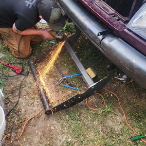
vertical cut beside diff


Filled gap, trussed

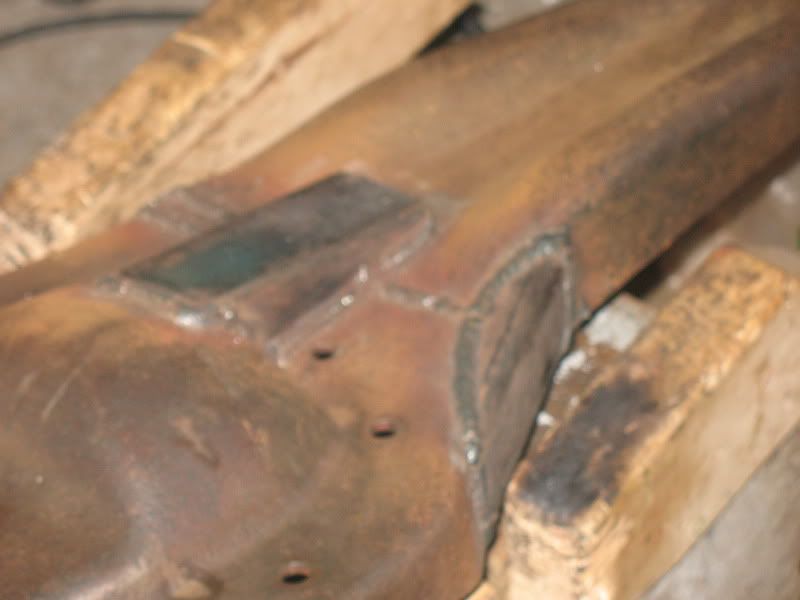
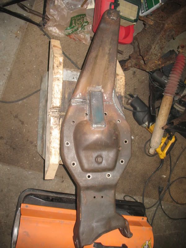
Fast forward 6 months and more research. Most setups look more "bent" than mine. I busted out the tape measure and calculator again, and sure enough my gap was off by .37 inches Here comes the old addage "measure twice cut once", but in my case it's "measure twice weld once"
I now have a cut and turn for 2.3" of spring, not the 4" I had planned for. So now i'm looking at my options. I can cut it up and start all over again. This would allow me to add a plate to the front of the beam as most guys do, and I probably should do. I'dd have to scrap my trusses and build new ones.
I can also run it as is with a 1.7" spacer, I will require a 1" spacer anyway with the coils I've got on hand. However, my alignment cam would be maxxed out. I could plate the inside of the beam. I could also push out the lower bj.
Looking for constructive input from those who may know better than me. I don't want to debate BJ vs C&T, please, as this is the route I've decided to go for reasons that appeal to me. I wheel tight trails and spend a good amount of time at full lock. I'm in no rush to finish this project, as I'm without a license for two years. I want a strong, safe and well performing setup. I'm planning on adding 44 outers, and maybe heim steering, but thats a whole 'nother thread.
EDIT: for anybody whose interested in this, for the drivers side D35 beam, every inch of additional spring height requires 1.9 degrees of camber correction. Thats additonal SPRING length, not LIFT height. It will be different (more correctionper inch req'd) for the shorter passenger beam, i'll post that spec when i tackle the p.s.
I decided, like a few others, to make my modfications inboard of the diff. I made some calculations, and determined by trgi I would need to build 7.66* of camber correction into the beams for 4" of spring, 6" lift. I made a vertical cut almost all the way through the beam and spread it to a distance I calculated, making a triangular gap. I used 3/16 plate to fill the gaps I'd made, added a couple "trusses", and burned it all together with a hobart 140.
Here are some pictures of my results:
vertical cut beside diff


Filled gap, trussed


Fast forward 6 months and more research. Most setups look more "bent" than mine. I busted out the tape measure and calculator again, and sure enough my gap was off by .37 inches
I now have a cut and turn for 2.3" of spring, not the 4" I had planned for.
 So now i'm looking at my options. I can cut it up and start all over again. This would allow me to add a plate to the front of the beam as most guys do, and I probably should do. I'dd have to scrap my trusses and build new ones.
 I can also run it as is with a 1.7" spacer, I will require a 1" spacer anyway with the coils I've got on hand. However, my alignment cam would be maxxed out. I could plate the inside of the beam. I could also push out the lower bj.
Looking for constructive input from those who may know better than me. I don't want to debate BJ vs C&T, please, as this is the route I've decided to go for reasons that appeal to me. I wheel tight trails and spend a good amount of time at full lock. I'm in no rush to finish this project, as I'm without a license for two years. I want a strong, safe and well performing setup. I'm planning on adding 44 outers, and maybe heim steering, but thats a whole 'nother thread.
EDIT: for anybody whose interested in this, for the drivers side D35 beam, every inch of additional spring height requires 1.9 degrees of camber correction. Thats additonal SPRING length, not LIFT height. It will be different (more correctionper inch req'd) for the shorter passenger beam, i'll post that spec when i tackle the p.s.
Last edited:

