
Introduction
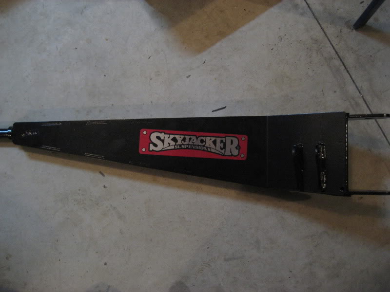
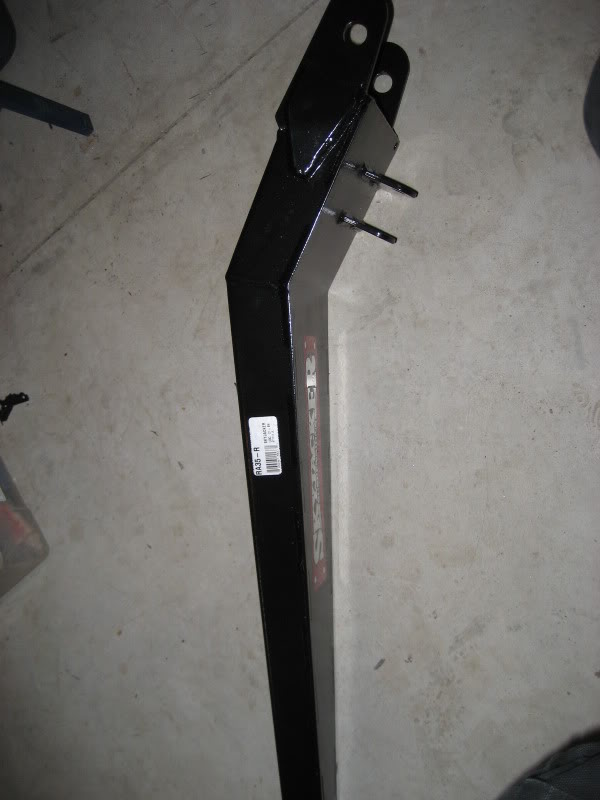
This page shows you how to install the Skyjacker Extended Radius Arms. The photo below is a comparison between the Skyjacker Extended Radius Arm (top) and stock radius arm (bottom).
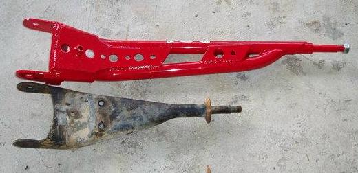
The longer radius arms increase wheel travel (up to 30%) and helps keep caster change to a minimum during suspension cycling. They also help triangulate and strengthen the suspension assembly.
Installation
TIP: A propane torch will soften and release the Loctite Ford puts on the studs to make them easier to come off.
The radius arm pivot bolts are going to take a 21mm and 22mm socket or wrench
The nut on the stud at the rear of the radius arm takes a 28mm socket or wrench.
Step 1) Remove the stock coil springs from both the driver and passenger side of vehicle. Unbolt the stock radius arms, remove the original radius arm frame brackets and remove from front axle housings.
Step 2) Place a jack under the Transmission and raise until it is touching transmission, but do not put a load on it. Remove the rivets and bolts that attach the existing Transmission Crossmember to the frame. If a torch is used to remove the rivets, be careful not to damage the rubber Body Mounts, wiring and hoses located inside the frame.
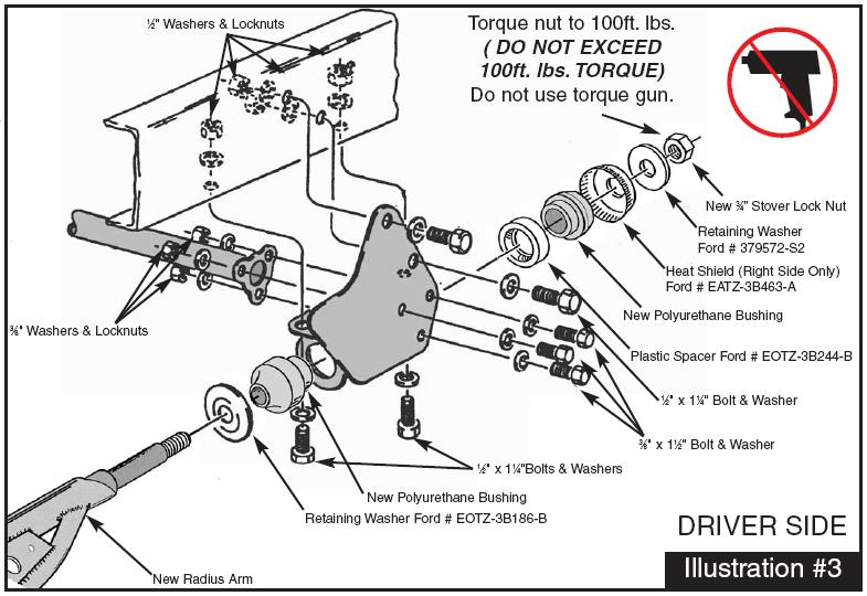
Step 3) Referring to illustration #3, align the driver side radius arm mounting bracket with two of the original holes on side of frame rail, and install 1⁄2 x 1-1⁄4″ supplied bolts. Torque these two bolts to specifications. Repeat on passenger side. On the underside hole locations, use the holes in new bracket as a guide and drill a 1⁄2″ hole through frame rail (there are 2 holes on each side to drill). Install 1⁄2 x 1-1⁄4″ supplied bolts in these 4 locations and tighten.
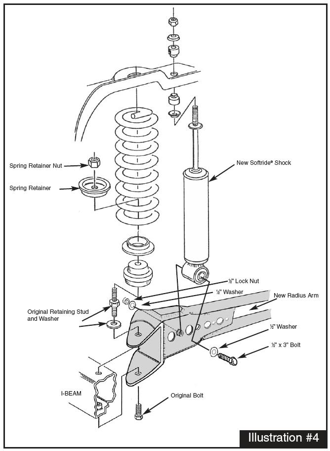
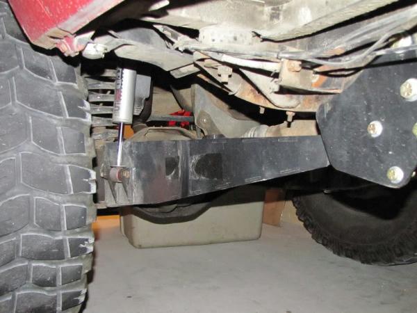
Step 4) Install the new radius arms to the front axles using existing hardware (see illustration #4). NOTE: Be sure to install the correct arm on the correct side with the correct side up (each arm is labeled accordingly).
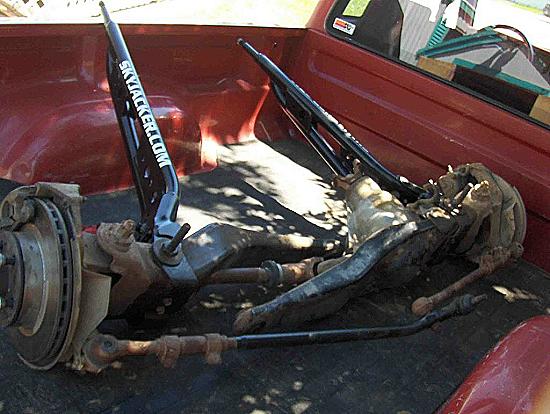
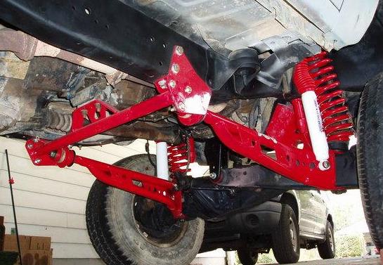
(Skyjacker radius arms installed on axle beams)
Step 5) Position the ends of radius arms into the new radius arm mounting brackets using the polyurethane bushings provided along with the original washers (as shown in illustration #3), and the 3⁄4″ stover nuts provided. Do not fully tighten at this time. Using the floor jack, raise axle and radius arms and check clearance on frame. Some models may need clearance at the OEM radius arm washer. Check again to be sure that all radius arm bushings and hardware are installed correctly. Apply Loctite and torque radius arm nuts to 100 ft. lbs. (DO NOT EXCEED 100 ft. lbs. TORQUE). Torque axle beam pivot bolts to 180 – 220 ft. lbs.
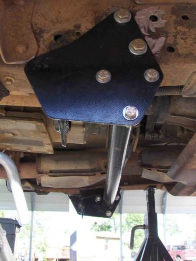
(Photo of Skyjacker crossmember installed)
Step 6) Position Transmission Crossmember between radius arm mounting brackets so that the upper mount aligns with the existing transmission bracket. Loosely fasten the new trans crossmember to the existing transmission bracket using existing hardware. Now loosely fasten new trans crossmember to each of the radius arm mounting brackets us the 3⁄8 x 1-1⁄2″ supplied bolts. Once all bolts are started, torque per specification chart.
Step 7) Remove the factory bump stops from the frame. Using a 3⁄8″ drill, enlarge holes and install the bump stop extensions using 3⁄8″ lock nuts provided. Install new polyurethane bump stops into the new extensions.
Step 8) Referring back to illustration #4, install new coil springs. Install new shocks as shown in illustration, using the 1⁄2 x 3″ supplied bolts. Tighten shock bolts and stems. Reinstall the front dirveshaft and torque the U-bolts to 12-15lbs.
Everything Installed
Tip: Set the rear of the radius arms in the crossmember and start the retaining nut on, but don’t tighten it up. Also, don’t tighten up the radius arms at the axle beams. Get the axle beams in their pivot/mounting points. Once everything is in its mounting point you can tighten it all up. This makes it much easier for all the components to move freely while you try and get everything lined up.
Torque Specifications
- Axle pivot Bracket Bolts
- Left axle arm ——————————- 83 to 113 ft. lbs.
- Right axle arm —————————– 155 ft. lbs.
- Axle Pivot bolt ———————————– 111 to 148 ft. lbs.
- Radius arm front bracket lower Bolt ——- 190 to 255 ft. lbs.
- Radius arm to front bracket upper Stud — 190 to 255 ft. lbs.
- Radius arm to front bracket front Bolts —- 15 to 27 ft. lbs.
- Radius arm to rear bracket Nut ————– 83 to 113 ft. lbs.
- Stabilizer bar link nuts ————————– 30 to 40 ft. lbs.
- Stabilizer bar bracket bolts ——————– 22 to 30 ft. lbs.
- Spring retainer nut ——————————- 70 to 100 ft. lbs.
Design Change
Sometime around 2011, Skyjacker changed the design of their Ford Ranger extended radius arms. The crossmember is the same, and the radius arm length should be the same as the original style, but the arms are boxed steel now instead of tube.
LINK: Skyjacker Suspensions
Conclusion
Extended radius arms are a must have modification for maximum wheel travel if you’re building a Ford Ranger for off-road. It’s not a difficult modification and well worth the money and effort.
Related Articles
Dana 28 / Dana 35 Axle Swap (Provides Info on Removing Radius Arms)
Ford Ranger TTB Extended Radius Arms
Build Your Own Extended Radus Arms
Sasquatch_Ryda’s Extended Radius Arms
Installing A Skyjacker Class II Suspension Kit
Last Updated:
About The Author
Jim Oaks is the founder of TheRangerStation.com, the longest-running Ford Ranger resource online since 1999. With over 25 years of hands-on experience building and modifying Ford Rangers — including magazine-featured builds like Project Transformer — Jim has become one of the most trusted authorities in the Ford Ranger off-road and enthusiast space.
Since launching TheRangerStation.com, Jim has documented thousands of real-world Ranger builds, technical repairs, drivetrain swaps, suspension modifications, and off-road adventures contributed by owners worldwide. TheRangerStation.com has been referenced in print, video and online by enthusiasts, mechanics, and off-road builders looking for practical, and experience-based information.