
Introduction
This page is based on Skyjacker’s Class II Suspension lift and uses their instructional page as a reference. This page is to give the Ranger owner an idea of what is involved in installing a Class II Suspension lift and uses their instructional page as a reference. This page is to give the Ranger owner an idea of what is involved in installing a Skyjacker lift and is not meant to be a replacement for any instructions that comes with the Skyjacker kit.
![]()
Front Installation
1. Block the rear wheels of the vehicle in front and behind the tires. Raise the front of the vehicle with a floor jack and support the frame with jack stands. Remove the front wheels and shock absorbers.
2. Remove the cotter pin and nut to disconnect the drag link assembly from the pitman arm and let the linkage hang. If your vehicle is equipped with a front anti-sway bar, loosen the bolts that attach the anti-sway bar to the radius arm brackets.
3. Mark the front driveshaft and the front differential yoke so that the driveshaft can be reconnected in its original position. Failure to do so may result in a driveline imbalance and subsequent vibration. Disconnect the front driveshaft at the u-joint and tape the caps to prevent them from falling off. Be very careful not to pull the rear end of the driveshaft forward out of its splines or damage may occur to the transfer case due to improper reinstallation. Secure the end of the driveshaft up and out of the way.
4. Disconnect both front brake lines at the calipers (be careful to save the crush washers as they will be reused if the original lines are reinstalled.) Hang the open ends of the brake lines as high as possible to keep the fluid from draining out. Cover the open ends of the brake lines and calipers to prevent loose dirt from entering the braking system. Disconnect the vent hose from the front differential housing.
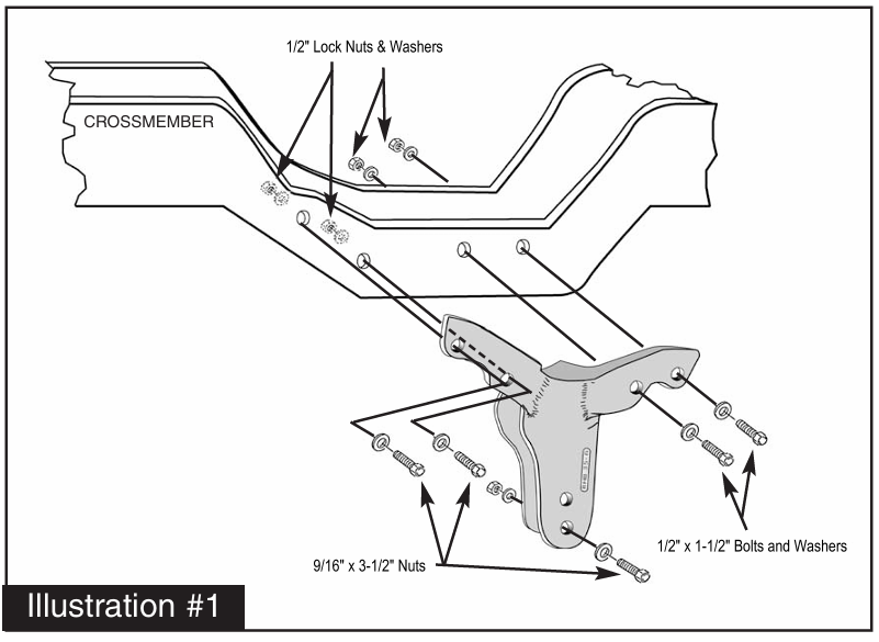
5. Place a jack under the passenger axle. Remove the passenger side axle beam bolt from the original bracket (located on the driver side of vehicle) and lower the axle down. Remove the original bracket from the front cross member. Using a 1/2″ drill, enlarge the original 4 holes and install the new replacement cast steel bracket (#RHB352-6, See Illustration #1) using the 1/2 X 1-1/2 bolts supplied. Torque the hardware to specifications. Next attach the passenger axle beam to the new drop bracket using the 9/16 X 3-1/2″ bolt supplied and tighten.
6. Move the jack to the driver axle beam and remove the axle beam bolt from the original bracket (located on the passenger side) and lower it down. Remove the original bracket from the front crossmember, saving the hardware. Referring to Illustration #2, attach new drop bracket (#LHB352-5) by reinstalling the original hardware into the original 4 holes (See “Existing-A” on illustration). Note: the original two holes labeled as “Existing-A” are for the existing two bolts on the back of the drop bracket. Be sure to install the original hardware in these two holes and tighten.
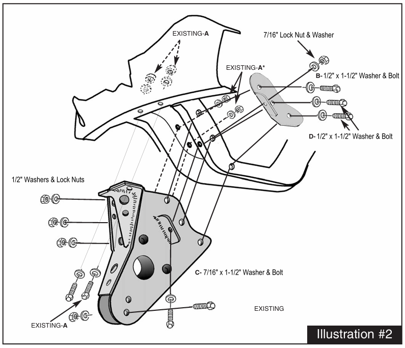
7. Now install a 1/2″ X 1-1/2″ supplied bolt labeled as “B” through the new bracket, crossmember, and the support bracket (#LHB352-5BP). Pivot the support bracket down so that the tab is flush against the crossmember lip. Torque these bolts to specifications. Drill 7/16″ hole for bolt labeled as “C” and install the supplied 7/16″ X 1-1/2″ bolt through the tab on the new drop bracket, crossmember lip and tab on support bracket and tighten.
8. Using the 2 holes in the cross member support bracket, drill a 1/2″ hole through the cross member and install the 1/2″ X 1-1/2″ supplied bolts, labeled as “D” through the support bracket, cross member and drop bracket. Next attach the driver axle beam to the new drop bracket using the original hardware and tighten. Check to be sure all bolts on drop bracket were tightened.
9. Remove the stock coil springs from both the driver and passenger side of the vehicle. Unbolt the stock radius arms, remove the original radius arm frame brackets and remove from the front axle housings.
10. Place a jack under the transmission and raise it until it’s touching the transmission, but do not put a load on it. Remove the rivets and bolts that attach the existing transmission cross member to the frame. If a torch is used to remove the rivets, be careful not to damage the rubber body mounts, wiring, and hoses located inside the frame rail.
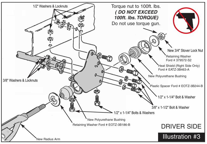
11.illustration #3, align the driver side radius arm mounting bracket with two of the original holes on side of frame rail and install 1/2″ X 1-1/4″ supplied bolts. Torque these two bolts to specifications. Repeat on the passenger side. On the underside hole locations, use the holes in new bracket as a guide and drill a 1/2″ hole through the frame rail (there are 2 holes on each side to drill). Install 1/2″ X 1-1/4″ supplied bolts in these 4 locations and tighten.
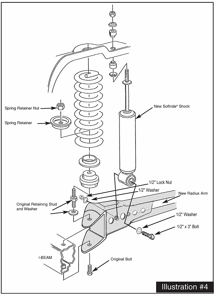
12. Install the new radius arms to the front axle using the existing hardware (See Illustration #4). Note: Be sure to install the correct side up (Each arm is labeled accordingly)
13. Position the ends of the radius arms into the new radius arm mounting brackets using the polyurethane bushings provided along with the original washers (As shown in Illustration #3) and the 3/4″ stover nuts provided. Do not fully tighten at this time.
14. Position the transmission crossmember between the radius arm mounting brackets so that the upper mount aligns with the existing transmission bracket. Loosely fasten the new transmission crossmember to the existing transmission bracket using the existing hardware. Now loosely fasten the new transmission crossmember to each of the radius arm mounting brackets using the 3/8″ X 1-1/2″ supplied bolts (on some models, one side of the new transmission crossmember may be too short. If so, insert the included 3-hole spacer between the crossmember and mounting bracket). Once all bolts are started, torque per specification chart.
15. Remove the factory bump stops from the frame. Using 3/8″ drill, enlarge the holes and install the bump stop extensions using 3/8″ lock nuts provided. Install the new polyurethane bump stops into the new extensions.
16. Referring back to Illustration #4, install the new coil springs. Install new shocks as shown in the illustration using the 1/2″ X 3″ supplied bolts. Tighten the shock bolts and stems. Reinstall the front driveshaft and torque the U-bolts to 12-15 ft. lbs.
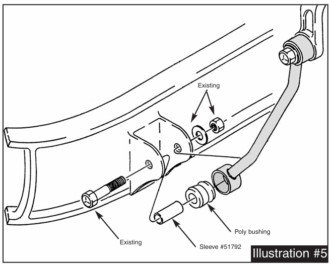
17. Install the two sway bar extensions, as shown in Illustration #5, using polyurethane bushings, steel sleeves #51792 and the original bolts.
18. Remove the original pitman arm from the steering box with a pitman arm puller. Failure to use the proper tool could result in damage to the steering mechanism. Install the supplied drop pitman arm (#FA400, for power steering models) into position, noting indexing marks, and tighten. Reconnect the drag link assembly to the new pitman arm.
19. Install the appropriate length brake lines at this time (also available from Skyjacker). Bleed the brakes to remove any air from the lines according to factory recommendations. Reinstall axle vent hose.
20. Reinstall the tires and lower the vehicle to the ground.
21. Cycle the steering left and right from lock to lock and check for any binding or interference. There should be a minimum of 1.0″ of clearance between the tires and the radius arms at full lock. If there is less than 1.0″, check to make sure you have the proper wheel offset and size. If necessary, the steering stop bolts may be adjusted out to 1.25″ maximum.
22. Front end realignment is necessary, so have a qualified alignment center realign the front end to factory specifications.
Rear Installation
23. Place a floor jack under the rear axle and raise the vehicle. Place jack stands under the frame to support the vehicle and remove the rear tires and shock absorbers.
24. Remove the axle U-bolts and lower the axle down a few inches. Care should be taken because when U-bolts are removed, the axle can be moved freely.
25.Block Installation Place the new block (tallest end towards the rear bumper) between the rear spring and the original factory block or degree shim, if so equipped. Raise the axle up being sure that the block pins are aligned and that the spring bolt is aligned in the block. Install and tighten the new rear U-bolts evenly (torque U-bolts 80-85 ft. lbs.). Install rear shock absorbers, tires, remove the jack stands and lower the vehicle down. Skip to final notes.
26. New spring installation: Remove the spring eye bolts and remove the original springs from the vehicle. Install new springs with the long end of the spring toward the rear bumper (also, thick end of bottom wedge shim goes toward the rear bumper, if equipped).
27. Raise the rear axle back up, aligning the spring pins into the axle housing. Install and tighten the new U-bolts evenly (torque U-bolts 80-85 ft. lbs.). Install the rear shock absorbers, tires and remove the jack stands and lower the vehicle down. Skip to final notes.
Final Notes
Before driving the vehicle, check to make sure the brakes are operating properly and need no further bleeding.
Inspect the components for tightness and for any damage periodically, especially after off-road use.
After installation is complete, double check that all nuts and bolts are tight. (Do not retighten nut and bolt where Loctite was used.) Check to ensure there is adequate clearance between all rotating, mobile and fixed members.
Rotate driveshafts and check for interference at differential yoke and cardan joint. If necessary, lightly dress castings(s) and/or U-joint tabs in order to eliminate binding.
On models with a rear carrier bearing, if a driveshaft vibration is present, the carrier bearing or it’s crossmember must be lowered.
Ensure there is adequate clearance between exhaust and brake lines, fuel lines, fuel tank, floorboard, and wiring harnesses. Check steering gear for interference and proper working order. Inspect brake lines for damage and adequate clearance. test brake system.
Have headlights readjusted to proper settings.
Front end alignment is necessary so have a qualified alignment center realign the front end to factory specifications.
Torque Specification Chart:
- 5/16″ Bolts—————————————13 Ft-lbs
- 3/8″ Bolts—————————————–35-37 Ft-lbs
- 7/16″ Fine Thread Bolts———————–55-58 Ft-lbs
- 1/2″ Fine Thread Bolts————————-85-90 Ft-lbs
- 1/2″ Rear U-Bolts——————————-80-85 Ft-lbs
- 9/16″ Fine Thread Bolts———————–115 Ft-lbs
- Spring Retainer – Upper Spring Seat——-13-19 Ft-lbs
- Radius Arm—————————————-180-220 Ft-lbs
- Lower Spring Retainer- Radius Arm———30-70 Ft-lbs
- Pitman Arm – Steering Gear Nut————–170-228 Ft-lbs
PDF Versions of Skyjacker Instructions
Skyjacker 1983-1997 Ford Ranger & 1990-1994 Ford Explorer 4WD Class II Instructions
Skyjacker 1983-1997 Ford Ranger 4WD Class I Instructions
About The Author
Jim Oaks is the founder of TheRangerStation.com, the longest-running Ford Ranger resource online since 1999. With over 25 years of hands-on experience building and modifying Ford Rangers — including magazine-featured builds like Project Transformer — Jim has become one of the most trusted authorities in the Ford Ranger off-road and enthusiast space.
Since launching TheRangerStation.com, Jim has documented thousands of real-world Ranger builds, technical repairs, drivetrain swaps, suspension modifications, and off-road adventures contributed by owners worldwide. TheRangerStation.com has been referenced in print, video and online by enthusiasts, mechanics, and off-road builders looking for practical, and experience-based information.