
Fuses protect your vehicle’s electrical system from overloading. If electrical parts in your vehicle are not working, the system may have been overloaded and blown a fuse. Before you replace or repair any electrical parts, check the appropriate fuses.
The following charts tell you which fuses protect each electrical part of your vehicle. If a fuse blows, all the parts of your vehicle that use that circuit will not work.
Once you have determined which fuses to check, follow the procedures under Checking and Replacing Fuses further down this page.
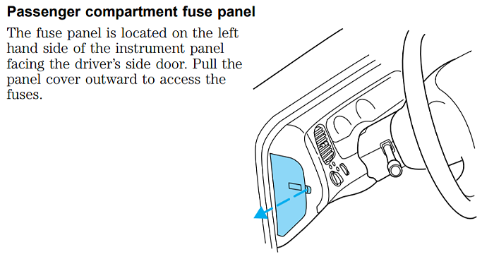
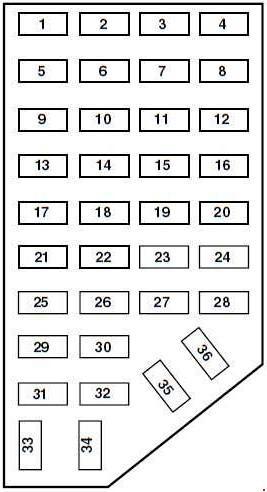
Passenger Compartment Fuse Panel
| No. | AMPS | Protected circuits |
| 1 | 5 | Power Mirror Switch |
| 2 | 10 | Daytime Running Lights (DRL), Back-up Lamps, Transmission, Passenger Air Bag Deactivation Switch, Blower Motor Relay |
| 3 | 7.5 | 2001-2002: Right Stop/Turn Trailer Tow Connector 2003: Left Stop/Turn Trailer Tow Connector |
| 4 | — | Not Used |
| 5 | 15 | 4×4 Control Module |
| 6 | 2 | 2002-2003: Brake Pressure Switch |
| 7 | 7.5 | 2001-2002: Left Stop/Turn Trailer Tow Connector 2003: Right Stop/Turn Trailer Tow Connector |
| 8 | — | Not Used |
| 9 | 7.5 | Brake Pedal Position Switch |
| 10 | 7.5 | Speed Control Servo/Amplifier Assembly, Generic Electronic Module (GEM), Shift Lock Actuator, Turn Signals, 4×4 |
| 11 | 7.5 | Instrument Cluster, 4×4, Main Light Switch, Truck Central Security Module (TCSM), GEM |
| 12 | — | Not Used |
| 13 | 20 | Brake Pedal Position Switch |
| 14 | 10 | ABS Control Module |
| 15 | — | Not Used |
| 16 | 30 | Windshield Wiper Motor, Wiper Hi-Lo Relay, Wiper Run/Park Relay |
| 17 | 20 | Cigar Lighter, Data Link Connector (DLC) |
| 18 | — | Not Used |
| 19 | 25 | Powertrain Control Module (PCM) Power Diode, Ignition, PATS |
| 20 | 7.5 | Generic Electronic Module (GEM), Radio |
| 21 | 15 | Flasher (Hazard) |
| 22 | 20 | Auxiliary Power Socket |
| 23 | — | Not Used |
| 24 | 7.5 | Clutch Pedal Position (CPP) switch, Starter Interrupt Relay |
| 25 | — | Not Used |
| 26 | 10 | Battery Saver Relay, Auxiliary Relay Box, Restraint Central Module (RCM), Generic Electroic Module (GEM), Instrument Cluster |
| 27 | — | Not Used |
| 28 | 7.5 | Generic Electronic Module (GEM), Radio |
| 29 | 20 | Radio |
| 30 | — | Not Used |
| 31 | — | Not Used |
| 32 | — | Not Used |
| 33 | 15 | Headlamps, Daytime Running Lamps (DRL) Module, Instrument Cluster |
| 34 | — | Not Used |
| 35 | 15 | Horn Relay if Not Equipped with Truck Central Security Module |
| 36 | — | Not Used |
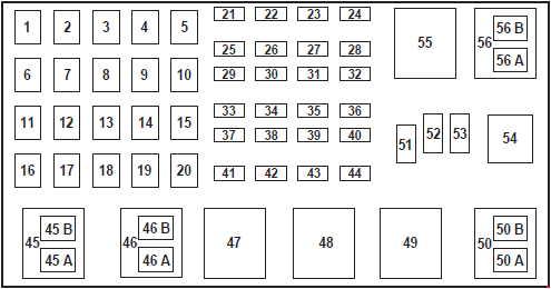
Power Distribution Box
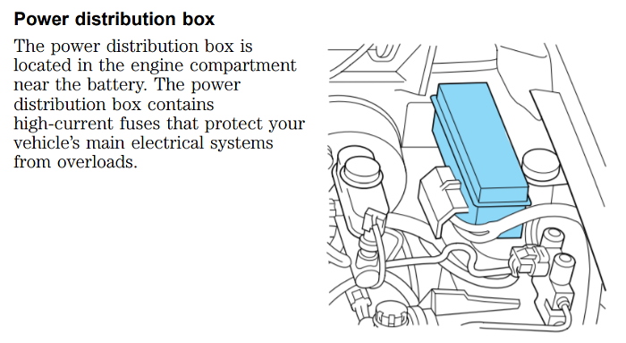
The power distribution box is located in the engine compartment on the drivers side near the fender.
2.3L Engine (above)
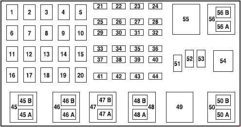
3.0L & 4.0L Engines (2001)(above)
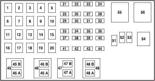
3.0L & 4.0L Engines (2002-2003)(above)
| No. | AMP | Protected circuits |
| 1 | 50 | I/P Fuse Panel |
| 2 | 50 | Amplifier (Tremor audio system only) |
| 3 | — | Not Used |
| 4 | — | Not Used |
| 5 | — | Not Used |
| 6 | 50 | ABS Pump Motor |
| 7 | 30 | Powertrain Control Module (PCM) |
| 8 | 20 | Power Door Locks and Remote Entry |
| 9 | — | Not Used |
| 10 | — | Not Used |
| 11 | 50 | Starter Relay, Ignition Switch |
| 12 | 20 | Power Windows |
| 13 | 20 | 3.0L and 4.0L engines: 4×4 Motor |
| 14 | — | Not Used |
| 15 | — | Not Used |
| 16 | 40 | Blower Motor |
| 17 | 20 | 2.3L engine: Auxiliary Cooling Fan |
| 18 | — | Not Used |
| 19 | — | Not Used |
| 20 | — | Not Used |
| 21 | 10 | PCM Memory |
| 22 | — | Not Used |
| 23 | 20 | Fuel Pump Motor |
| 24 | 30 | Headlamps |
| 25 | 10 | A/C Clutch Solenoid |
| 26 | — | Not Used |
| 27 | — | Not Used |
| 28 | 30 | 4WABS Module |
| 29 | — | Not Used |
| 30 | 15 | Trailer Tow |
| 31 | 20 | Foglamps, Daytime Running Lamps (DRL) |
| 32 | — | Not Used |
| 33 | 15 | Park Lamp |
| 34 | — | Not Used |
| 35 | — | Not Used |
| 36 | — | Not Used |
| 37 | — | Not Used |
| 38 | 10 | Left Headlamp Low Beam |
| 39 | — | Not Used |
| 40 | — | Not Used |
| 41 | 20 | Heated Oxygen Sensors |
| 42 | 10 | Right Headlamp Low Beam |
| 43 | — | 2.3L engine: (Resistor) |
| 44 | — | Not Used |
| 51 | — | Not Used |
| 52 | — | Not Used |
| 53 | — | Diode: Powertrain Control Module (PCM) |
| Relay | ||
| 45A | Wiper HI/LO | |
| 45B | Wiper Park/Rim | |
| 46A | 2.3L engine: Fuel Pump 3.0L and 4.0L engines (2002-2003): Fuel Pump |
|
| 46B | 2.3L engine: Trailer Tow 3.0L and 4.0L engines (2001): Front Washer Pump 3.0L and 4.0L engines (2002-2003): Trailer tow |
|
| 47 | 2.3L engine: Starter 3.0L and 4.0L engines (2001): A/B – Not Used |
|
| 47A | 3.0L and 4.0L engines (2002-2003): A/C clutch solenoid | |
| 47B | 3.0L and 4.0L engines (2002-2003): Front washer pump | |
| 48 | 2.3L engine: Auxiliary Cooling Fan | |
| 48A | 3.0L and 4.0L engines: Fog Lamps | |
| 48B | 3.0L and 4.0L engines: Fog Lamp Relay | |
| 49 | 3.0L and 4.0L engines (2001): Starter | |
| 50 | Not Used | |
| 50A | 3.0L and 4.0L engines (2001): Not Used | |
| 50B | 3.0L and 4.0L engines (2001): Fuel Pump | |
| 54 | Powertrain Control Module (PCM) | |
| 55 | Blower | |
| 56 | 3.0L and 4.0L engines (2002-2003): Starter | |
| 56A | A/C Clutch Solenoid | |
| 56B | 2.3L engine: Front Washer Pump 3.0L and 4.0L engines (2001): Trailer Tow |
|
Checking and Replacing Fuses
If you need to check a fuse, follow these steps:
1. Find the fuse panel, which is located in the left end of the instrument panel. The power distribution box (described earlier in this section) is found in the engine compartment, mounted on a bracket attached to the drivers side fender apron.
To access the fuse panel, remove the fuse panel cover by inserting your finger in the divot and pulling on the cover. The underside of the cover contains four spare fuses. A fuse pulling tool is located in the lower right corner of the fuse panel in case you need to replace a blown fuse.
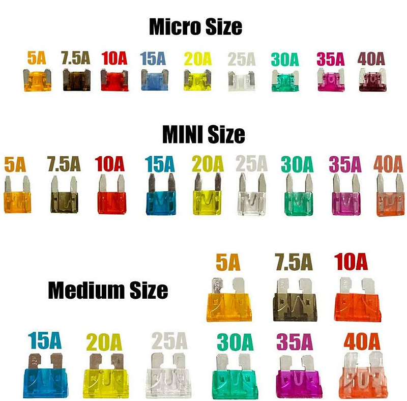
Color Coded: The spare fuses for your vehicle are color coded as follows:
- 10 amp — red
- 15 amp — light blue
- 20 amp — natural
- 30 amp — light green.
See further down on this page for examples
2. On the fuse panel cover, find the number of the fuse you want to check. The diagram on the cover tells you where to
locate the fuse on the panel.
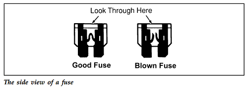
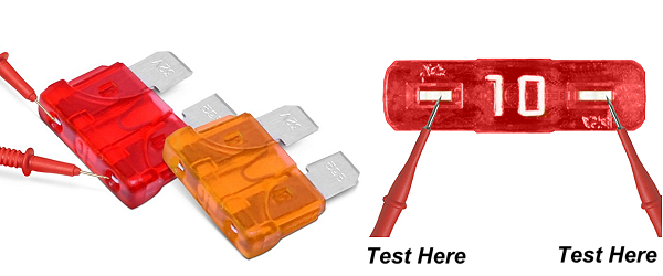
3. Check the fuse to see if it is blown. Look through the clear side of the fuse to see if the metal wire inside is separated. If it is, the fuse is blown and should be replaced.
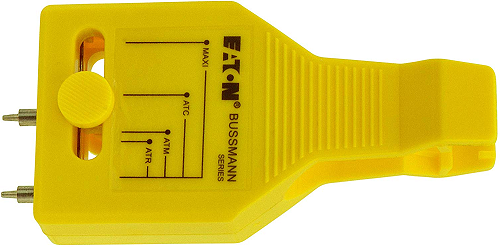
Another method for testing fuses is to use a Bussmann fuse tester. There’s no need to remove the fuse from the holder. You simply adjust the prong width on the tester to line up with the bare metal spots on the end of the fuse, and then watch for the indicator light to glow signaling that the fuse is good.
4. Replace the fuse with one that has the right amperage rating
*WARNING Always replace a fuse with one that has the specified amperage rating. Using a fuse with a higher amperage rating can cause severe wire damage and could start a fire.
5. Put the fuse panel cover back on.
Even after you replace a fuse, it will continue to blow if you do not find what caused the overload. If the fuse continues to blow, have your electrical system checked.
Fuse Color / Ratings:
As mentioned above, fuses are color coded to their AMP rating. See the image below for examples.
Related Articles:
About The Author
Jim Oaks is the founder of TheRangerStation.com, the longest-running Ford Ranger resource online since 1999. With over 25 years of hands-on experience building and modifying Ford Rangers — including magazine-featured builds like Project Transformer — Jim has become one of the most trusted authorities in the Ford Ranger off-road and enthusiast space.
Since launching TheRangerStation.com, Jim has documented thousands of real-world Ranger builds, technical repairs, drivetrain swaps, suspension modifications, and off-road adventures contributed by owners worldwide. TheRangerStation.com has been referenced in print, video and online by enthusiasts, mechanics, and off-road builders looking for practical, and experience-based information.