
Introduction
Here’s how you can get rid of that terrible TFI Ignition and replace it with a Duraspark Ignition.
The 2.8L V6, as found in Rangers and Bronco II’s from 1983 to 1985, are saddled with a rather bizarre fusion of EFI and carburetion in the form of the EEC-IV controlled Motorcraft carburetor and TFI ignition (Thick Film Integrated). Some people choose to replace this ignition with an earlier Duraspark ignition. The stock “feedback carburetor” should also be replaced with an earlier non emission controlled 2 BBL carburetor to make this conversion function properly. You can get a 2 BBL carburetor from a Ford 2.8L that had a Duraspark ignition or upgrade to a Holley 350 CFM 2 BBL carburetor P/N 0-7448. This will eliminate the need for and make the stock EEC nonfunctional. This is not a complicated swap. Not as complicated as people make it sound.
Forum Help: If you still need help after reading this page visit: Duraspark conversion (Forum Thread)
Quick Overview
You’re going to be replacing the factory ignition with a Duraspark distributor, coil and ignition module. To wire the new ignition on a 1983-1984 Ford Ranger or 1984 Ford Bronco II you simply plug it in to an existing plug and then wire the coils (+) ‘BAT’ to the Red/Light Green wire that’s hot when the key is on.
There’s more splicing involved when wiring the ignition on a 1985 Ranger / Bronco II. Basically, you’ll be powering the Modules Red wire in the plug with the Rangers Red/Light Green wire and the Modules White wire with the Ranger / Bronco II Red/Light Blue wire. The coils (+) ‘BAT’ is powered by the Ranger / Bronco II Red/Light Green wire.
(Duraspark Components)
Parts Needed
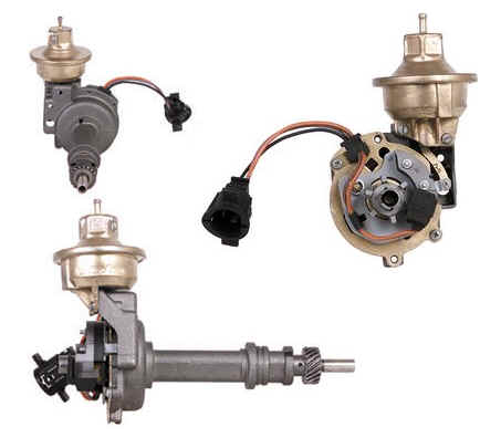
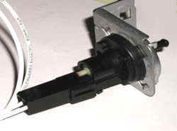
Ford 2.8L Duraspark Distributor
OE Part Numbers:
- 75TF12100MA
- 75TF12100NA
- 76TF12127EA
- 76TF12127GA
- 77TF12100AA
- 77TF12100CA
- 77TF12100DA
- 77TF12100HA
Aftermarket Part Numbers:
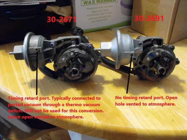
- Cardone: 30-2691
According to ‘Uncle Gump’ in your forum, you can use a 30-2671 by leaving the vacuum port open (See image below).
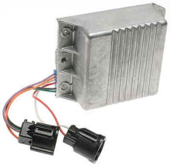
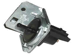
Ford Duraspark Ignition Module (Note 2 Connectors Not 3)
OE Part Numbers:
- 12334611
- 19110488
- D6AB12A199A1B
- D6AB12A199A2B
- D6AE12A199A1A
- D6AE12A199A1B
- D6AE12A199A1C
- D6AE12A199A2A
- D6AE12A199A2B
- D6AE12A199A2C
- D6AE12A199AA
- D6AZ12A199A
- D6AZ12A199B
- D6TE12A199A1A
- D6TZ12A199A
- D7AZ12A199B
- D8AE12A199A1E
- D8VE12A199A1A
- D8VE12A199A1B
- D8VE12A199A1C
- D8VE12A199A2A
- D8VE12A199A2B
- D8VE12A199A2C
- D9VZ12A199A
- E1FZ12A199A
- E8PF12A199AA
- E8PF12A199AB
- E9VZ12A199A
- E9YZ12A199A
- F2PF12A199AA
- F2PZ12A199A
- F2PZ12A199AA
This ignition module was used in a wide range of Fords from 1976-1986.
Aftermarket Part Numbers:
- United Motor Products: M184
- Wells: 6H1012
- Standard Motor Products: LX203
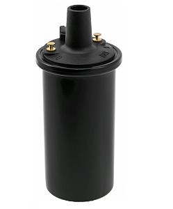
Ignition Coil
OE Part Numbers:
- 12336831
- 3230427
- 33004522
- 8933004522
- D5AZ12029A
- J3230427
Aftermarket Part Numbers:
- Wells: 5C1023
- Walker Products: 9201010
- United Motor Products: C314
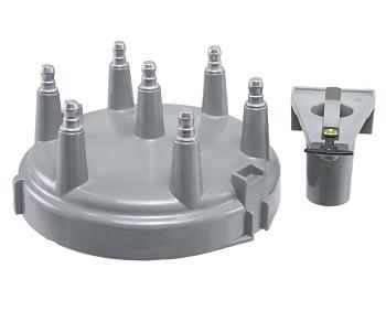
Distributor Cap & Rotor
OE Part Number:
- F2104
Aftermarket Part Number:
- Wells: 3D1109
- Wells: 3D1109A (Premium)
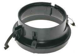
Distributor Cap Adapter
OE Part Numbers:
- 12321934
- 88921848
- D7DZ12A217A
- E3DZ12A217A
Aftermarket Part Numbers:
- Standard Motor Products: FD155
- Wells: 4D1002
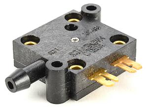
Vacuum Switch (For A4LD Setups)
- GM Vacuum Switch P/N 14014519
- TCI Replacement Vacuum Switch Kit # 890-376600
Optional Harness Parts
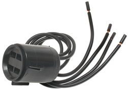
ECM Harness Connector (4 Prong) Napa P/N echec127
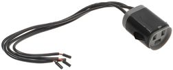
ECM Harness Connector (3 Prong) Napa P/N echec72
Non-Feedback Carburetor
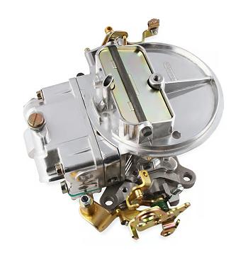
Holley 0-7448SA 350 CFM Performance 2BBL Carburetor
The 1978 Pinto carb works well on stock engines. If your 2.8 is more performance oriented, or has headers and upgraded exhaust, you may want to use the 350CFM Holley 0-7448SA 2BBL carb. This carb comes jetted for a V8. A good jet size to start tuning a 2.8 with is #54 jets.
Doing The Conversion – Removing The Junk
Remove the entire wiring harness from the engine except for the Electric Choke, Engine Temp and Oil Pressure sending units wiring. Leave the wiring to the alternator as well. If you have air conditioning you will have a couple wires going to that as well. . This should remove about 95% of the wiring out of the way. Just lay it over the passenger fender for now. You may have to cut some of the wires such as the Red with Light Green wire that supplies power to the TFI module as well as the ECM. There is usually a big splice where it is routed to the necessary locations. Remove all the vacuum lines lines to the EGR and carburetor. If you have not already removed the smog pump now would be the perfect time to do so. Just plug the lines that go back to the exhaust manifolds and cat converter. Remove the EGR valve and make a metal block off plate out of thin sheet metal to block off the EGR port on the carburetor spacer. Reinstall the EGR valve just to plug the hole. Install a vacuum cap on top of the EGR valve’s vacuum port.
Remove the plug wires and cap from the distributor. Bump the starter to get cylinder #1 at top dead center. Unplug the TFI connector from the distributor. Remove the distributor by removing the 13mm hold down bolt on the back of the intake manifold. Gently pull out the distributor.
Assemble the new distributor by screwing on the rotor and install the distributor cap collar. Make sure to grease the O-ring on the new distributor before sliding it in. Slide in the distributor making sure to keep the rotor pointed at the #1 piston. If it will not slide all the way down try turning the crankshaft with a ratchet just a bit and it should engage with the cam gear then. Reinstall the distributor hold down bracket and bolt but don’t tighten yet.
Mount The Duraspark Ignition Module
Find a suitable place to mount the Duraspark box on the driver’s side fender. Connect the wiring harness you got from the donor vehicle to the distributor and route it over to the Duraspark box and connect it up. The distributor end has (4) pins and the Duraspark end has (3) as the green wire goes to the (–) side of the coil.
Power to the Duraspark Module 1983-1984 Ranger / Bronco II (‘Plug-n-Play’)
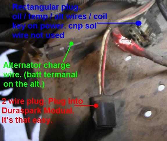
If you have a 1983 or 1984 Ranger / Bronco II you’re in luck. There is a factory round Duraspark style plug with Red and White wires at the drivers fender well. It will plug in to the plug with White and Red wires on the Duraspark Ignition Module. Don’t be alarmed when you notice that a Red wire plugs into a White one and vice versa. This is correct.
The (+) ‘BAT’ side of the Coil is the only place you have to splice into a wire. On the driver’s fender well, there is another connector, square in shape and gray in color that has either a Brown wire with Pink markings or a Red wire with Light Green. These wires should be hot when the key is on. This wire needs to go to the (+) ‘BAT’ terminal on the ignition coil.
Power to the Duraspark Module 1985 Ranger / Bronco II
Many found, that after installing the module, distributor, harness, and coil, that the plug with the Red wire and the Light Green wire on the 1985 Ranger / Bronco II that connects to the Red and White wires on the Duraspark Ignition Module does not supply power to the module like it should. It was also found that without some cutting and splicing, that the engine would also not even turn over. This isn’t that difficult to overcome.
Both of the wires (Red & White) in the plug on the Duraspark Ignition Module are both used for power input to the module:
Red wire (Modules 2-wire plug) – This wire needs power when the Key is ON.
White wire (Modules 2-wire plug) – This wire needs power from the key in the START position.
Plugs To Look For
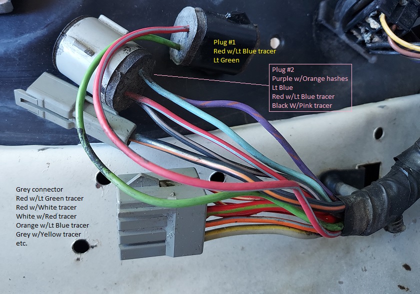
There are two round Duraspark style plugs at the driver’s fender well:
- Plug #1 – 2-Wire Duraspark type female round plug with a Red/Light Blue wire and Light Green wire going in. The Red/Light Blue wire has power in the START position.
- Plug #2 – 4-Wire Duraspark type female round plug. The 4-wires are:
- 2 – Purple/Orange wires – Power to the back-up lamp switch.
- 1 – Red/Light Blue Stripe wire – Part of cranking circuit with key in START position.
- 1 – Dark Blue wire – No longer used
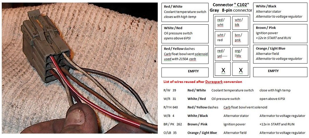
- Plug #3 – Gray rectangle plug with a Red/Light Green wire. The Red/Light Green wire has power in the START & RUN position.
Connections To Make
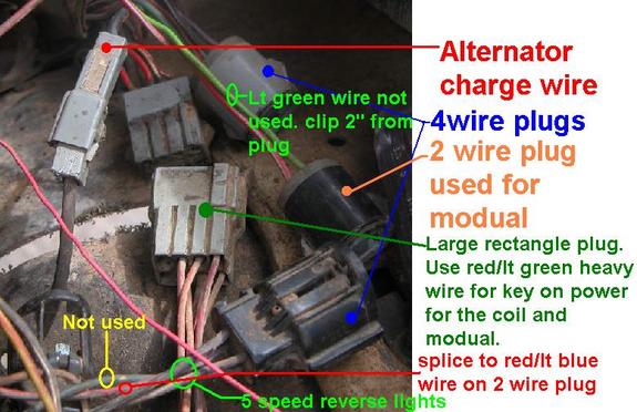
1) Cut the Light Green wire going in the Duraspark style 2-wire plug (#1 in pic below) with enough room to wire on to it. Tape off the other end. Find the Red/Light Green wire in the gray rectangle plug (#3 in pic below). Splice the Light Green wire in plug #1 (pic below) into this Red/Light Green wire. When the plug is connected to the Duraspark Ignition Module, it will line up with the Red wire in the Modules plug to supply power when the key is ON.
2) Run a wire from the Red/Light Green wire to the (+) ‘BAT’ side of the Ignition Coil to supply power when the key is ON.
3) The 2-wire plug (#1 in pic below) and 4-wire plug (#2 in pic below) have Red/Light Blue wires and need to be spliced together. They are part of the cranking circuit. Without splicing the two Red/Light Blue wires together, the engine’s starter will not operate. The Red/Light Blue wire in the plug when connected to the Duraspark Ignition Module will line up with the White wire in the Modules plug to supply a signal when in the START position.
Connecting The Distributor
Your distributor has an Orange/Yellow, Purple/Light Blue & Black/Light Green wire coming off of it.
Your Duraspark Ignition Module has an Orange/Yellow, Purple/Light Blue, Black/Light Green, and Dark Green/Yellow wire coming off of it.
You can go to a salvage yard and pick up a wire harness from a late 70’s or very early ’80 Ford car/truck with the Duraspark ignition to run between the Distributor and the Ignition Module. Your other option is to simply make your own harness with 12ga wire and female connectors and match the plugs up color to color.
Note that the Ignition Module has a Dark Green/Yellow wire that the Distributor does not. The Dark Green wire connects to the (-) ‘TACH’ side of the Ignition Coil.
Vacuum Lines & Plug Wires
Hook up a vacuum line from the distributor to the carburetor above the carburetor plates to get ported vacuum not at the back of the carburetor or on the intake manifold vacuum tree. Plug the vacuum port on the front of the intake under the carburetor if you are not using the Motorcraft 2150 carburetor.
Install the distributor cap and connect the plug wires. Now fire it up and set the timing. Then tighten the distributor hold down bolt and you are done.
Using The A4LD Transmission With This Conversion:
The A4LD automatic overdrive transmission is a Ford C3 automatic transmission modified with the addition of overdrive. The first version of this transmission has a single electronic control solenoid located in the valve body that moves a valve allowing transmission fluid to flow into the TCC (torque converter clutch) circuit of the transmission. When fluid flows through this circuit it causes the engagement of the TCC. This process is known as “converter lockup”. The timing of this lockup is controlled by the ECA (Electronic Control Assembly). The purpose of the clutch is to create a direct positive connection between the engine and transmission. This reduces slippage, thereby limiting the workload on the engine which improves power transmission to the driveline, and fuel economy. Normally the clutch should only engage at a steady highway speed (approximately 45+ MPH) with the transmission shifted into overdrive.
The later models incorporated electronically controlled overdrive as well. This was achieved with the addition of one or more control solenoids for this process.
Ford only offered the first version of this transmission for 2.8L powered Rangers and Bronco II’s in 1984, and 1985. In 1986 the OD position on the shift selector was removed, and replaced with an electronic OD shift button. Vehicles equipped with the early version of this transmission require additional steps to complete the Duraspark conversion.
Toggle Switch Method
It could be possible to control the converter lock up with a toggle switch. The only drawback is you have to judge the correct time to engage it and disengage it yourself. The control solenoid is similar to a relay switch. It is controlled by two wires, positive and negative. The positive wire receives a constant 12V. The negative wire is a controlled ground. This means that with a functional ECA, the computer uses a switching circuit to connect and disconnect the ground. This completes, or breaks the circuit. If you’d like to try the “Toggle Switch Method” this method this is how to do it.
Locate the solenoid connector on the transmission toward the drivers side front on the top of the pan lip
Unplug it and using a test light find the 12V power lead. Now you know the other wire is the ground.
Cut the ground wire about 4″ back from the connector. On the connectors side, strip the jacket on the ground wire about 1/2″ back. Plug the connector back in and ground the wire you just stripped to the transmission. If you here a click then you know that the solenoid is functional. Unplug the connector again.
Using a length of 16AWG wire long enough to reach into the vehicles passenger compartment butt connect this wire to the ground wire using a 16AWG butt connector. Plug the connector back in.
Route the wire up into the passenger compartment near a suitable switch mounting location. Connect the wire to one terminal of a SPST (Single Pole Single Throw) 12V toggle switch. Using a short piece of 16AWG wire connect one end to the other switch terminal and the remaining end to a good ground. Mount the switch and test it out.
Pressure Switch Method
The second method we have for you utilizes a pressure switch. This is an automatic engagement solution. The pressure switch is installed in the governor portion of the transmission body. When the fluid pressure reaches the switch tolerance the switch closes completing the circuit and energizing the solenoid. This should occur at highway speeds (45+ MPH) when shifted into overdrive
Use the same instructions in the above procedure to determine which wire is the controlled ground.
1) On the passenger side of the transmission toward the back at the bottom near the tail extension locate a protrusion with a hole in the center which resembles a bolt boss. This is the governor area of the transmission. Using a 3/16″ drill bit coated with grease to collect shavings carefully drill in the center of this hole until it punches through into the internal chamber
2) Start the engine and let it run for about a few seconds which will force out any remaining shavings (transmission fluid will stream out forcing the remaining debris out).
3) Using an 1/8″ pipe thread tap, tap threads into the boss about 1/2″ deep. It may be necessary to open up the hole a little prior to tapping. Use the size drill bit recommended on the tap. Run the engine again to force out remaining debris.
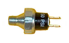
4) Thread in a 44-52 PSI pressure switch into the hole
5) Run a hot wire to one side of the transmission plug and the other wire to the controlled ground pressure switch. Drive the vehicle and once you reach highway speed (45+MPH) shift into overdrive and pay close attention to the feel of the shift. If it feels firm and you don’t experience erratic “in and out” OD shifting then you were successful. If it does shift “in and out” erratically you may need to experiment with different tolerance pressure switches until you find what works best for you
You can also see this article: A4LD Pressure Switch For Lock Up Torque Convertor
Vacuum Switch
The last way to control the solenoid is with a Vacuum Switch. The control solenoid is similar to a relay switch. It is controlled by two wires, positive and negative. The positive wire receives a constant 12V. The negative wire is a controlled ground. This means that with a functional ECA, the computer uses a switching circuit to connect and disconnect the ground. This completes, or breaks the circuit.
Locate the solenoid connector on the transmission toward the drivers side front on the top of the pan lip.
Unplug it and using a test light find the 12V power lead. Now you know the other wire is the ground.
Cut the ground wire about 4″ back from the connector. On the connectors side, strip the jacket on the ground wire about 1/2″ back. Plug the connector back in and ground the wire you just stripped to the transmission. If you here a click then you know that the solenoid is functional. Unplug the connector again.
Butt connect a new wire to the end of the ground wire you stripped coming from the solenoid connector and run the wire into the drivers compartment.
You need to install a switch where the stop light switch is at the brake pedal. This new switch should normally be open so power runs through it until it’s pressed. We haven’t found any Ford part numbers but we know that the GM brake switch P/N 25524848 has two connections; one for the brake lights that’s closed and opens to send current to the brake lights when you press it. The other is open for the cruise control and interrupts (breaks the connection) when you press it disengaging the cruise control. We don’t know for sure if this can be mounted on the Ranger / Bronco II.
From the brake switch, the wire needs to go to a Vacuum Switch (GM P/N 14014519). From the vacuum switch the wire goes to ground.
Once you complete this, the torque converter will go into lock-up except for when the vacuum is low (under throttle) or when the brakes are applied.
NOTE: The GM Vacuum Switch P/N 14014519 is discontinued. You can find them on ebay but they’re pretty expensive. I’ve read where people have used the TCI Replacement Vacuum Switch Kit # 890-376600.
Thanks To
- ‘Totalled-E.B.BII’
- James Pringle
- ‘Budro’
For their contributions to this page over time.
Diagrams
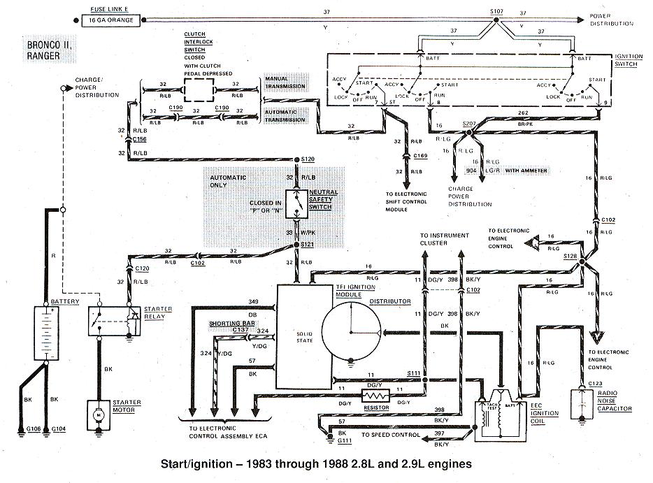
1983 – 1988 Ford Ranger / Bronco II Ignition Diagrams #1
1985 Ford Ranger . Bronco II Ignition Diagram #2 (PDF)
1979 Ford Duraspark Ignition Diagrams (PDF)
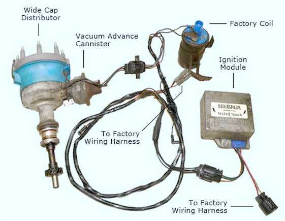
Typical Duraspark Ignition
Related Articles
Powerspark Ignition Conversion
Ford Ranger / Bronco II 2.8L V6 Engines
2.8L Chevy TBI Swap on to Ford 2.8
Ford EEC-IV/TFI-IV Electronic Engine Control Troubleshooting
200 Horsepower From Ford 2.8 Liter V6
Last Updated:
About The Author
Jim Oaks is the founder of TheRangerStation.com, the longest-running Ford Ranger resource online since 1999. With over 25 years of hands-on experience building and modifying Ford Rangers — including magazine-featured builds like Project Transformer — Jim has become one of the most trusted authorities in the Ford Ranger off-road and enthusiast space.
Since launching TheRangerStation.com, Jim has documented thousands of real-world Ranger builds, technical repairs, drivetrain swaps, suspension modifications, and off-road adventures contributed by owners worldwide. TheRangerStation.com has been referenced in print, video and online by enthusiasts, mechanics, and off-road builders looking for practical, and experience-based information.