
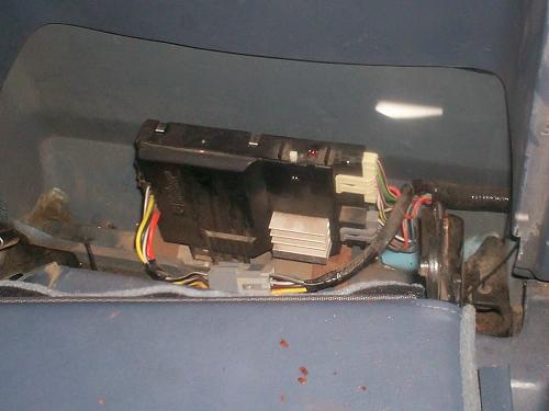
If your 4WD Ranger has a push button 4wd system (automatic, no manual lever), than it’s going to have a 4WD Shift Module mounted somewhere in the cab. The photo above shows one mounted under the jumpseat on the drivers side of an extended cab. For some reason, some people confuse these with factory amplifiers for the stereo. Maybe it’s because of the aluminum fins that protrude from it.
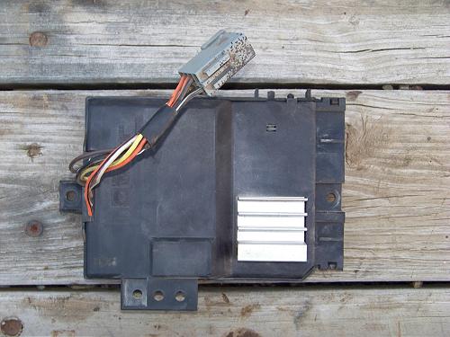
Here’s a better view:

They can generally be found located:
- Regular Cab: Driver side rear corner of cab
- Super Cab: Under the rear drivers side jump seat.
Note: The 1995-2000 Ford Ranger 4×4 are equipped with a Generic Electronic Module (GEM) that incorporates several different modules in to one. This module is located in the dash behind the radio.
Note: The 2001 Ford Ranger uses a 4WD module located behind the passenger side kick panel.
Diagnosing 4WD problems involving this module:
I made the specifics of this apply to a 1994 Ranger with a BW1354 case, but I’m sure that the basic concepts can be applied to other years.
I can’t cover every practical situation that you’ll encounter with the 4×4 not working. This is written to be a guide for most situations……its going to be long, and assumes that you can
1) use a test light to check fuses and
2) use a volt meter to check for power/grounds/resistance in different circuits.
DO NOT JAM A TEST LIGHT / THICK VOLT METER LEADS INTO ANY CONNECTOR. You will ruin that connector or its ability to maintain a solid connection with the other pin. Go to the store and pick up a pack of small T-pins (look in the sewing department). They work great for this sort of thing or back probing connectors.
If you can’t use a volt meter, you can still do some basics – just don’t expect to find something like a corroded wire at some connection that’s causing your 4×4 system failure.
First, are you sure that you’ve got no 4×4? This article is going to cover the electrical shifting system, and will not touch on your 4×4 hubs and how to fix them.
Before you get in over your head, and realize you’ve got bad hubs and not a bad 4×4 shift system, do yourself a favor and put the truck up on jack stands (all 4 tires off the ground). Shift the truck into 4×4, and with the motor running put the trans into drive. Let out on the brake, and let the truck idle in drive…..check to see if both drive shafts are turning. If they are, yet you’ve got no front wheels spinning, you’ve got a hub issue. If one is spinning it’s because you’ve got an open differential.
Assuming that your front drive shaft is not spinning, you’ve got a 4×4 engagement problem…….now you’ve got to do some diagnostics.
Diagnostics:
1. Check to make sure all fuses for the system are good. There are two fuses that supply power to your 4×4 shift system – one located under the hood, the other under the dash. The fuse under the hood is a 20 amp maxi fuse. The fuse under the dash is a 15 amp ATO fuse. On the 1994 Rangers its located in fuse position 7.
a. If they’re good, go to step 2.
b. If they’re bad, you’ve got a short somewhere in the system. Try to replace the fuse, and see what happens. If it blows, you’ve got something shorted to ground in the circuit. If you know how to use a volt meter, you should know how to find a short in the circuit, and will need a wiring diagram to do so.
2. If all the fuses are good, the next step is to run the 4×4 module self diagnostic. The 4×4 module is located behind the driver’s side rear jump seat on super-cab models, but as far as the other locations I don’t really know. This module will have three connectors going to it – one will be a pig tail, the other two will be located on the right side of it (side towards the front of the truck). These two connectors must be removed to diagnose the module.
With the key in the off position, remove these two connectors from the module.
Next, turn the key on with the engine off. On top of the module is a white rectangular button located next to a red LED….push the button and watch the LED.
a. If it flashes, this indicates the module is working properly. Go to step 3.
b. If it lights up and stays on, it indicates that the module is likely bad.
c. If nothing happens, it means the module is either bad, or has no ground/power.
In either of these instances (b or c) power and ground should be verified before scrapping a 4×4 module.
The 4×4 module receives its power/ground through the 8 pin pigtail connector.
Pin Position 1 = Open, no wire
Pin Position 2 = Solid Black = Ground
Pin Position 3 = Orange/Black = Logic Ground
Pin Position 4 = Orange = Transfer Case Motor Control (Clockwise) 2H-4H-4L
Pin Position 5 (across from position 4) = Yellow = Transfer Case Motor Control (Counterclockwise) 4L-4H-2H
Pin Position 6 = Brown = Electromagnetic Clutch (Feed)
Pin Position 7 = White/Purple = Ignition Run and Crank (Start) Feed (Fused)
Pin Position 8 = Dark Green/Light Green = 20A Maxi-Fuse in Power Network Box (under hood fuse)
3. With the two connectors still unplugged from the module, the next step is to verify the 4×4 dash switch input. Take the 5-wire connector, the one with the gray connector color, and check the following:
a. Connect an ohmmeter between terminals 1 (White/Light blue wire) and 2 (Dark Blue wire). Then depress the 4×4 (2H-4H) switch. The ohmmeter should indicate a low resistance value (less than 50 ohms) while the switch is being depressed. If this occurs, the switch feed to and from the module is good.
b. Connect an ohmmeter between terminals 1 and 3 (orange/light blue wire). Then depress the LOW RANGE switch. The ohmmeter should indicate a low resistance value (less than 50 ohms) while the switch is being depressed. Again, if this occurs, the 4 low switch is good.
c. Connect a test lead between terminal 4 (brown/white wire) and ground. Turn the ignition switch to RUN and observe the indicator lights. The LOW RANGE light in the instrument panel and LOW RANGE indicator light on the switch should illuminate. This indicates the 4×4 lo switch/dash lights are good.
d. Connect a test lead between terminal number 5 (grey wire) and ground. Turn the ignition switch to RUN and observe the indicator lights. The 4×4 light in the instrument panel and 4×4 light on the switch should illuminate. This indicates the 4×4 hi lights/dash lights are good.
e. If any of these tests fail, you will have to check the wires from the module to the back of the switch for continuity. This is done easily by removing the dash switch and connecting an ohmmeter between the same color wires, with one lead at the module and the other at the switch. A resistance value of 10 ohms or less is good, any more indicates excessive circuit resistance. If all 5 wires have low resistance between the switch and module, the switch is bad and must be replaced.
4. The next step will check the circuitry to the shift motor. Your shift motor must be hooked up for this to work. Grab the 8 wire connector that is unplugged from the 4×4 module. It will be tan in color. Check the following:
a. Connect an ohmmeter between terminal 1 (red/light blue for manual trans vehicles, red/white for auto trans vehicles) and ground. On a vehicle equipped with a manual transmission, depress the clutch pedal and observe the ohmmeter. The ohmmeter should indicate a low resistance (less than 50 ohms) while the clutch pedal is being depressed. If the vehicle is equipped with an automatic transmission, shift the transmission into NEUTRAL and observe the ohmmeter. The ohmmeter should indicate a low resistance (less than 50 ohms) while the transmission selector lever is in the NEUTRAL position. This ensures that the Park/Neutral switch or Clutch pedal switch is good (needed for 4 lo shifts).
b. Connect an ohmmeter between terminals 2 (light green) and 3 (light blue). The ohmmeter should indicate a low resistance reading (235-470 ohms). This will check the continuity of the speed sensor that is located in the transfer case. The speed sensor picks up the rotating speed of the transfer case rear output shaft from two notches that are cut in opposite sides of the outer ring of the clutch housing.
c. Connect an ohmmeter between terminal 8 (yellow/white) and terminals 4 (violet), 5 (white), 6 (brown/white) and 7 (orange/white), respectively. Refer to the following chart for the appropriate ohmmeter readings in each transfer case position.
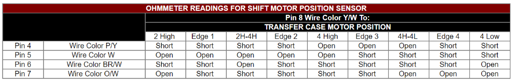
NOTE: Edge positions and Mid-Shift positions are valid motor codes that the module will respond to; however, any motor found in one of these positions should be replaced/torn apart and cleaned/inspected to prevent the overshooting of shift points.
SHORT is a “low” resistance reading on the ohmmeter (zero ohms).
OPEN is a “high” resistance reading on the ohmmeter (infinity).
5. Up to now, the following should have been verified:
a. You verified that:
1) All fuses are good
2) The 4×4 module tested ok, and has power/ground (make sure the pigtail connector isn’t corroded – is common among rust belt trucks)
3) The 4×4 switch tested ok
4) The shift motor circuitry tested ok
b. With the key off, reconnect the two connectors. Make sure the key is off.
c. The next step is to verify that the module is supplying voltage to the shift motor. To do this, you’ll either need a second person or long volt meter leads. Crawl under the truck. Find the connector that connects to the shift motor. Leave it connected. Back probe the solid orange wire through the connector located on the shift motor side. You are essentially checking for voltage at this pin to ensure that it is getting voltage, and that the connector is good. Next, turn the key to run and push the 4×4 switch. You should see 12 volts on the volt meter. If not, ensure that the volt meter has a good ground and try again.
1) If you’ve got a 12 volt signal, go to step d.
2) If you’ve got nothing still, go to step 6.
d. If you have a 12 volt signal, the next thing to do is verify that the motor has a good ground as well. Back probe the solid orange wire on the connector as well. Again, check for a 12 volt signal using the yellow wire. This ensures that the module is grounding the other side of the motor, allowing for current to flow through the motor. If the shift motor still doesn’t work (you can’t hear/feel it spin) then it’s probably bad. You can remove it from the transfer case and make sure you can spin the transfer case manually using a pair of pliers. If you can, then it’s a good bet the motor is bad. If you can’t, you’ve got other issues and the t-case probably needs some internal repair…..the shift motor may be alright after all, and the major (internal) issue must be repaired first.
1) If you didn’t receive a 12 volt signal, then the module isn’t grounding the motor for some reason, and could be bad. Continuity from the orange/yellow wires at the shift motor connector to the 8 wire pig-tail connector from the module must be checked.
6. If in step five you had no power signal, even when you grounded the volt meter to something other than the module itself, you need to 1) make sure the wires have continuity between the 4×4 module and shift motor, and 2) make sure that the module is sending a 12v supply to the 4×4 switch. To verify issue 1, see part d-I in step 5. To verify issue 2:
a. With all connectors plugged into the module, back probe the dark blue wire (terminal 2) on the 5 pin gray connector – the one on the lower right side of the module. Make sure you DO NOT ground your back probe out while doing this. With this pin back probed, turn the key on. Check for a 12 volt signal there while pushing the 4×4 switch. If you have 12 volts there, your module is sending a 12 volt supply to the 4×4 switch.
1) If no voltage is present there, turn the key off and back probe terminal 1 (white/light blue) on the same connector. Again, it is more crucial here that this is not grounded. If you ground this pin out with the key on, even for 1/16th of a second, your module could be ruined. Now that you’ve ensured your back probe is not and cannot be grounded out, check for voltage by simply turning the key on.
1. If you have voltage here, but did not in part 6a you must verify continuity between the module and 4×4 switch – refer to step 3.
2. If you have no voltage here, make sure the module has power and ground. If it does, it’s probably bad.
That should be a fairly decent start on system diagnosis, and I’ll bet completing those steps will tell you what is wrong with your system. Again, there could be some weird issue, and you’ll have to make a post for more info.
Related Article:
Checking 4WD Shift Module Circuits (1994-Older)
Last Updated:
Co-Author:
This procedure was performed and documented by TRS forum member Chris1044 who submitted the article for the author to publish at The Ranger Station for other Ford Ranger owners to use.
About The Author
Jim Oaks is the founder of TheRangerStation.com, the longest-running Ford Ranger resource online since 1999. With over 25 years of hands-on experience building and modifying Ford Rangers — including magazine-featured builds like Project Transformer — Jim has become one of the most trusted authorities in the Ford Ranger off-road and enthusiast space.
Since launching TheRangerStation.com, Jim has documented thousands of real-world Ranger builds, technical repairs, drivetrain swaps, suspension modifications, and off-road adventures contributed by owners worldwide. TheRangerStation.com has been referenced in print, video and online by enthusiasts, mechanics, and off-road builders looking for practical, and experience-based information.