• Welcome Visitor! Please take a few seconds and Register for our forum. Even if you don't want to post, you can still 'Like' and react to posts.

Smart Junction Box connectors


vbrad511

Well-Known Member
Joined
Jan 6, 2008
Messages
155
City
Springfield, Illinois
Vehicle Year
1997
Transmission
Manual
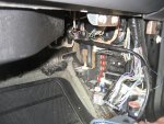
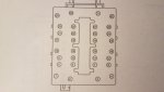
Hey all, I'm in the process of stereo and alarm install on my '11 Ranger. I'm at the point of needing to tap into a wire on the SJB, and wanted to pull the connector to verify the pin count. I've never been into a box like this, so i'm looking for help getting the connector off. It's got a kind-of "T" handle jobber on it. Do I just pull that "T" back for the whole thing to release? I'm not wanting to break anything, so I figured I'd better ask before I just started pulling on things.
 
Yes, you just pull the little levers to release the connections but why not just use fuse taps instead of splicing off the harness directly?
 
Yes, you just pull the little levers to release the connections but why not just use fuse taps instead of splicing off the harness directly?

It's the door trigger I'm looking to verify. Charts I've seen show it to be a green/purple wire, pin 6, in a 32 pin connector. I've found a green/purple wire, but with the mess of wires there I want to verify where it connects in the box (pin 6). I'd hate to hook something up wrong and have something (expensive) go up in smoke.
 
Fair enough, I thought you were just tapping into something for a power circuit. Definitely good to double check.

Put a little dielectric grease on the connectors when you put them back.
 
Looks like I'm having issues finding the correct plug/wire for this door trigger. It's supposed to be a green/purple wire, in a 32-pin black plug, pin 6. There are two green/purple wires in the box. One in a gray plug that seems to be a full time ground, and one in a black plug that seems to be a very thin wire, and is nowhere near what should be pin position 6. If anybody's been through this, or has suggestions how I should proceed, please chime in.
 

Attachments

  • IMG_0371 - Copy sized.jpg
    IMG_0371 - Copy sized.jpg
    133.7 KB · Views: 198
Last edited:
Dunno if you have the pinouts as they are numbered. If not hope this helps.

The door switch circuit should be a ground. When the door is open it should show grounded, when door closed it should be open loop. (I think!) Im not a electrical expert but thats how door jamb switches generally function.

My diagram shows #6 pin door ajar on the black connector, 20 guage wire, green and violet.
 

Attachments

  • Screenshot_20190204-214415_Gallery.jpg
    Screenshot_20190204-214415_Gallery.jpg
    414.2 KB · Views: 166
Last edited:

Sponsored Ad


Sponsored Ad

TRS Events

Member & Vendor Upgrades

For a small yearly donation, you can support this forum and receive a 'Supporting Member' banner, or become a 'Supporting Vendor' and promote your products here. Click the banner to find out how.

Latest posts

Recently Featured

Want to see your truck here? Share your photos and details in the forum.

Ranger Adventure Video

TRS Merchandise

Follow TRS On Instagram

TRS Sponsors


Sponsored Ad


Sponsored Ad


Amazon Deals

Sponsored Ad

Back
Top