I have more info and understand the electronics part now...
Yes. In the sensor, the resistor tells the computer "I'm here and functioning." The switch contacts say "deploy the bags!".
In the airbags them selves, the resistance is something like nichrome wire (or could be nichrome wire) which heats up quickly and ignites the charge. But the microcomputer is probably also looking for that resistance to know that the airbag device is in the circuit.
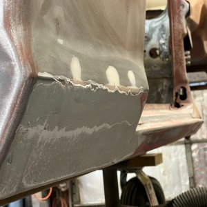
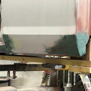
This came in as I was typing. So now I'm just trying to understand the repair. Are we talking about rear half doors on an extra cab? Just wondering why the harness would care about a door with extra features that it didn't know about...
But either way, I do feel like 2.3 ohms sounds like a sensible value for such a circuit. I'll just quote what I found in another forum:
"The
squib that detonates the air bag has a resistance of 2.3Ω if it is intact and "ready to blow". The RCM passes a small current limited test signal (just a few ma, it takes 5+ amps to light up the squib) through the squib to detect this resistance, and confirm that the air bag is connected and ready to go.
By placing the resistors across the harness connectors the RCM believes the air bags are there and "good to blow" while doing the test--a bit safer than doing the test (after the repair) with live explosives."
I'm thinking Ford probably didn't have 20 designs for this type of circuit, and that explanation sounds completely reasonable to me in every way.
Edit: ok, another quick search indicates that it's virtually universal across Ford airbags that the computer is looking for between 2 and 5 ohms. I think any standard value in the middle there should make the computer happy, like 2.7 ohms