
Transfer Case Identification & 4WD Guide
Transfer cases come in a wide variety of designs, sizes, and configurations. While their basic purpose is to transfer power from the transmission to the front and rear axles, the way they accomplish this can vary considerably. Some are designed for part-time 4WD, while others provide full-time 4WD or all-wheel drive. They can be chain-driven or gear-driven, use mechanical or electronic shifting, and incorporate features such as center differentials, viscous couplings, or electronically controlled clutches.
If you’re specifically looking for the transfer cases used in the 1983-2011 Ford Ranger or 1984-1990 Ford Bronco II, including detailed applications and information about the Borg-Warner BW1350 and BW1354, see our Ford Ranger & Bronco II Transfer Cases guide.
What Is a Transfer Case?
A transfer case is a mechanical unit that transfers power from the transmission to the vehicle’s front and rear axles. In a 4WD vehicle, the transfer case is mounted behind the transmission and uses a combination of gears, chains, shafts, clutches, differentials, and other components to distribute engine power to the drive axles.
A transfer case can provide several different operating ranges and drive modes, depending on its design. A typical two-speed transfer case provides high range for normal driving and low range for situations requiring increased torque at the wheels. Depending on the transfer case, the driver may also be able to select 2WD, 4WD, neutral, or different combinations of part-time and full-time four-wheel drive.
The transfer case has two primary power outputs. The rear output sends power toward the rear axle, while the front output sends power to the front axle when 4WD is engaged. The location and design of these outputs vary between transfer cases and are important when identifying a transfer case or determining whether it will work in a particular vehicle.
Transfer cases are built in several different configurations. Some use a chain to drive the front output, while others use gears. Some are designed strictly for part-time 4WD, while others incorporate a center differential, viscous coupling, or electronically controlled clutch to allow the front and rear axles to operate at different speeds. Transfer cases may also use mechanical shift levers, electric shift motors, or electronically controlled systems to select their operating modes.
Transfer Case Operating Modes
Transfer cases can operate in several different ways. The terminology can be confusing because four-wheel drive (4WD), full-time four-wheel drive, and all-wheel drive (AWD) do not all describe the same type of system. Understanding how the transfer case connects the front and rear axles is important when identifying a transfer case or deciding how it can be used.
Part-Time 4WD
A part-time 4WD transfer case mechanically connects the front and rear drivetrains when four-wheel drive is selected. In most traditional part-time systems, there is no center differential to allow the front and rear axles to rotate at different speeds.
When traveling in a straight line, the front and rear driveshafts can rotate at approximately the same speed. When the vehicle turns, however, the front and rear axles travel different distances and naturally need to rotate at different speeds. Because the transfer case has them mechanically coupled, the difference in speed must be absorbed elsewhere in the drivetrain, primarily through tire slip.
This can cause driveline windup or bind, especially on dry pavement where the tires cannot easily slip. For this reason, traditional part-time 4WD should generally be used on loose or slippery surfaces such as dirt, gravel, mud, snow, or ice where the tires can release the difference in speed.
Part-time transfer cases commonly provide 2WD High, 4WD High, and 4WD Low, although the available modes vary by transfer-case design.
Full-Time 4WD
A full-time 4WD transfer case is designed to allow the front and rear drivetrains to rotate at different speeds while remaining in four-wheel drive. This is typically accomplished with a center differential or another mechanism that allows some speed difference between the front and rear outputs.
Because the front and rear axles are not rigidly locked together, a full-time system can generally be used on dry pavement without the driveline bind associated with a traditional part-time system.
Some transfer cases combine full-time and part-time operation, allowing the driver to select between an unlocked mode for normal driving and a mechanically locked mode for situations where maximum traction is needed.
The newer Ford F-150, Bronco, 2024+ Ford Ranger and other Fords are a good example of this. The models that offer full-time 4WD use a specialized two-speed automatic transfer case. This system operates differently than traditional part-time four-wheel drive. When set to 4A, the vehicle uses an electronically controlled clutch to monitor traction. It runs in 2WD most of the time to save fuel but immediately sends power to the front wheels the moment it detects your rear tires slipping. This is why people build Ford F-150 4×4’s with full-time 4WD into performance trucks. While in 4A, they can send power to all four wheels during heavy acceleration and launches.
All-Wheel Drive (AWD)
All-wheel drive (AWD) systems are designed to automatically distribute power to the front and rear axles rather than requiring the driver to manually select four-wheel drive.
AWD transfer units can use several different methods to distribute torque. Depending on the design, they may incorporate a center differential, viscous coupling, electronically controlled clutch pack, or other torque-distribution mechanism. Some AWD systems operate primarily as front-wheel or rear-wheel drive until additional traction is needed, while others continuously distribute torque between the two axles.
Unlike a traditional part-time 4WD system, many AWD systems are designed to remain engaged during normal driving on high-traction surfaces.
AWD is not the same as the Ford full-time 4WD 4A setting that we previously discussed. While Ford’s full-time 4WD relies on a heavy-duty truck transfer case that can be locked into traditional, rigid 4×4 modes, standard AWD is a permanently active, lighter system designed for cars and crossovers that lacks low-range gearing. This makes AWD highly optimized for seamless, everyday street safety rather than heavy-duty towing or rock crawling.”
Selectable Part-Time and Full-Time Systems
In the automotive industry and engineering terminology, systems are categorized based on what the transfer case is capable of doing and how much control the driver has over those capabilities. Ford’s 4A-equipped layout satisfies all requirements of this classification:
1. It is “Selectable” – The driver is not forced into a single operating state. Using a physical dial or buttons on the dashboard, you have the manual authority to completely alter the mechanical behavior of the drivetrain. You can explicitly select between two-wheel drive high, automated four-wheel drive, locked high-range, or locked low-range.
2. It offers “Part-Time” Modes – When you switch the dial to 2H (2WD High), 4H (4WD High), or 4L (4WD Low), the system behaves exactly like a traditional, rigid part-time 4WD setup:
2H uncouples the front wheels completely to eliminate drag and save fuel.
4H and 4L mechanically lock the front and rear driveshafts together at a strict 50/50 power split. Because there is no internal slip allowed in these settings, they represent true “part-time” modes that will cause driveline binding and tire scrubbing if used on dry pavement.
3. It offers a “Full-Time” Mode – When you switch the dial to 4A (4WD Auto), the system transitions into a “full-time” capable system. Because the transfer case utilizes an electronically controlled, variable multi-plate clutch pack instead of a rigid mechanical lock, it can safely allow the front and rear axles to rotate at different speeds. This eliminates drivetrain damage and allows you to leave the vehicle in 4WD continuously on high-traction surfaces like bone-dry asphalt.
Because a single transfer case architecture gives you the freedom to choose between traditional part-time operational modes (2H/4H/4L) and a pavement-safe, active on-demand full-time mode (4A), it sits squarely within the Selectable Part-Time and Full-Time industry definition.
4WD Transfer Case Settings
2H / (Two-Wheel Drive High)
Operation: Sends 100% of the engine’s power exclusively to the rear wheels.
Mechanism: Disengages the front driveshaft and uncouples the front hubs to eliminate unnecessary mechanical drag.
Best Used For: Everyday driving on dry, high-traction pavement. This mode minimizes drivetrain wear and maximizes fuel economy.
4A (Four-Wheel Drive Auto)
Operation: Delivers continuous, on-demand full-time four-wheel drive capability.
Mechanism: Utilizes an electronically controlled multi-plate clutch pack inside the transfer case. The system monitors wheel speed and throttle inputs, automatically shifting torque to the front wheels the instant rear slip is detected or anticipated. Because the internal clutch can slip dynamically, it prevents drivetrain binding.
Best Used For: Variable or unpredictable road surfaces—such as patchy snow, ice, heavy rain, or wet gravel—where you can safely transition between dry asphalt and slick conditions without driver intervention.
4H (Four-Wheel Drive High)
Operation: Locks the front and rear driveshafts together to provide continuous power to all four wheels simultaneously.
Mechanism: Completely locks the transfer case clutches or gears into a rigid 50/50 torque split. Because there is no internal slip allowed between the front and rear axles, the tires must be able to loose traction slightly to prevent driveline wind-up.
Best Used For: Severe, low-traction environments like deep snow, heavy mud, loose sand, or off-road trails. It should never be engaged on dry pavement, as doing so causes tire hopping and severe component strain.
4L (Four-Wheel Drive Low)
Operation: Maintains the rigid 50/50 locked torque split of 4H while engaging a low-range gear reduction set.
Mechanism: Routes power through an extra set of planetary gears inside the transfer case, multiplying engine torque significantly while reducing the vehicle’s overall ground speed.
Best Used For: High-load, low-speed, extreme off-road situations. This includes crawling over large rocks, climbing steep grades, descending treacherous slopes, or extracting a heavy trailer from deep mud or a steep boat ramp.
How Does An Electric Shift Transfer Case Operate
An electronic shift transfer case replaces the traditional manual floor lever with a dashboard switch (or dial) and an electric actuator motor. Instead of using raw physical force to pull internal shift forks into place, it relies on a dedicated computer module, electrical signals, and electric gear motors to transition between 2WD, 4WD High, and 4WD Low. Here is a step-by-step breakdown of exactly how the system operates
1. The Core Components
To understand the process, you have to look at the three main components that handle the translation from a finger-press to a mechanical gear change:
The Dash Switch / Selector: A simple low-voltage rotary dial, button, or switch on your dashboard.
The Control Module: A dedicated computer (often called the Transfer Case Control Module, or TCCM) or an integrated chassis computer (like Ford’s GEM) that acts as the system’s brain.
The Shift Motor Assembly: An electric DC motor bolted directly to the exterior rear half of the transfer case. Inside this assembly is the electric motor, a small reduction gear set to multiply torque, a positional sensor (encoder assembly), and a small electromagnetic clutch.
2. The Operational Sequence: Shifting into 4WD High
When you are driving down a dirt road and flip your dash switch from 2H to 4H, the following chain reaction happens in milliseconds:
Signal Input: The dash switch sends a specific electrical resistance or CAN-bus message to the Control Module indicating you want 4WD High.
Safety Checks: The module checks current vehicle conditions. For a 4H shift, it typically looks at the vehicle’s speed sensors to ensure you are travelling below a safe threshold (e.g., under 55 or 60 mph).
Synchronization (The Electric Clutch): Because you are moving, the transmission output shaft and rear driveshaft are spinning fast, but the front driveshaft is stationary. Bolted inside the case is a small electromagnetic synchronization clutch. The module sends power to this clutch first. The clutch magnetically grabs the front output sprocket and brings the stationary front driveshaft up to the exact operating speed of the rear driveshaft.
Motor Rotation: Once the front and rear shafts are spinning at the identical speed (synchronized), the computer feeds power to the external Shift Motor.
Moving the Shift Cam: The shift motor rotates a small shaft that extends inside the transfer case. This shaft turns a specialized cam dial or helical track. As this cam rotates, its machined grooves force the internal mechanical shift forks to slide laterally across the mainshaft, engaging the lock collar that sends permanent mechanical power to the front chain drive.
Position Verification: Inside the electric motor assembly, a multi-pin encoder wheel or contact disc tracks the motor’s exact degree of rotation. It sends a feedback loop back to the module saying, “The shift motor has completed a 45-degree rotation and is successfully locked in 4H.” The module then illuminates your dashboard “4WD” light.
3. The Low-Range Sequence: Shifting into 4WD Low
Shifting into 4-Low introduces a mechanical gear reduction (planetary gear set) to maximize torque. Because this change requires meshing completely different gear ratios, the operation changes significantly to protect the drivetrain from grinding:
Strict Logic Constraints: When you select 4L on the dash, the Control Module will refuse to execute the command until very strict physical conditions are met. It checks the vehicle speed sensors to ensure you are at a dead stop (0–3 mph) and checks the transmission range sensor to confirm you have shifted the transmission into Neutral (or depressed the clutch pedal on a manual).
Executing the Shift: Once the transmission is completely unloaded in Neutral, the computer triggers the shift motor to rotate much further (often a full 180-degree sweep compared to the short 4H movement).
Planetary Engagement: The rotating shift cam pushes the primary shift fork out of direct drive and forces a heavy-duty reduction hub to slide into the teeth of the internal planetary gear assembly. This routes input torque through a sun gear and planet gears, multiplying your torque output (typically by a factor of 2.48:1 or 2.72:1) while lowering your top vehicle speed.
Confirmation: The encoder senses the motor has safely completed its maximum travel, and the computer changes your dash indicator to “4WD LOW”.
Popular Transfer Cases
Thousands of different transfer-case models and variations have been produced over the years. This guide does not attempt to document every transfer case ever made. Instead, the following sections focus on popular and commonly encountered transfer cases, particularly those found in Ford, Jeep, GM, Dodge, and other 4×4 applications and those frequently used in drivetrain swaps and custom builds.
Transfer cases within the same model family can have significant differences in input shaft configuration, output location, shift mechanism, gearing, and internal components. The model name alone is therefore not always enough to determine whether a particular case will work for a specific application.
BorgWarner Transfer Cases
BorgWarner has produced a wide range of transfer cases for Ford and other manufacturers. Many BorgWarner cases use aluminum housings and chain-driven front outputs, although the company has produced transfer cases with several different designs and operating systems.
Popular BorgWarner transfer cases include:
- BW1345
- BW1350
- BW1354
- BW1356
- BW1359
- BW4404
- BW4405
- BW4406
The BW1350 and BW1354 are particularly important to Ford Ranger and Bronco II owners. For detailed information about their applications, identification, specifications, and differences, see Ford Ranger & Bronco II Transfer Cases.
The BW4404, BW4405, and related cases represent a different type of transfer-case design and were used in applications with full-time, all-wheel-drive, or electronically controlled torque-distribution systems.
New Process and New Venture Transfer Cases
New Process Gear (NPG) and later New Venture Gear (NVG) produced many of the most widely used transfer cases in American 4×4 vehicles.
Popular models include:
- NP203
- NP205
- NP208
- NP231
- NP241
- NP242
- NV271
- NV273
These transfer cases range from relatively compact chain-driven units to heavy-duty gear-driven cases. The NP205, for example, is a large cast-iron, gear-driven transfer case known for its strength and durability, while the NP231 is a compact chain-driven case that became extremely popular in Jeep and other 4×4 applications. The NP242 is notable because it combines multiple operating modes, including part-time and full-time four-wheel drive.
Dana/Spicer Transfer Cases
Dana/Spicer produced several important gear-driven transfer cases, particularly for older 4×4 vehicles.
Popular models include:
- Dana 18
- Dana 20
- Dana 300
These cases are generally recognizable by their gear-driven construction and are widely used in restoration projects, drivetrain swaps, and custom off-road builds. The Dana 20 and Dana 300 are particularly popular with builders because of their compact gear-driven design, aftermarket support, and ability to be modified for custom applications.
Aftermarket Transfer Cases
Aftermarket manufacturers have also developed transfer cases specifically for high-performance and custom 4×4 applications.
The Atlas II, produced by Advance Adapters, is one of the best-known examples. Unlike many factory transfer cases, the Atlas II was designed from the beginning with custom drivetrain applications in mind and is available in multiple configurations and low-range ratios.
Aftermarket transfer cases can provide features such as:
- Multiple low-range ratios
- Different input configurations
- Different output configurations
- Custom clocking options
- Twin-stick operation
- Heavy-duty gears and shafts
When comparing an aftermarket transfer case with a factory unit, consider not only the transfer case’s strength and gearing but also its input compatibility, output configuration, physical dimensions, mounting requirements, and available adapters.
Common Transfer Case Chart
Transfer Case Type & Low Ratios |
|||
| Model | Mode | Drive | Low Ratio |
| NP203 | Full-Time | Chain Drive | 2.00:1 |
| NP205 | Part-Time | Gear Drive | 1.96:1 |
| NP207 | Part-Time | Chain Drive | 2.61:1 |
| NP208 | Part-Time | Chain Drive | 2.61:1 |
| NP219 | Part-time/Full-Time | Chain Drive | 2.61:1 |
| NP228 | Part-Time | Chain Drive | 2.62:1 |
| NP229 | Part-Time/Full-Time | Chain Drive | 2.62:1 |
| NP231 | Part-Time | Chain Drive | 2.72:1 |
| NP241 | Part-Time | Chain Drive | 2.72:1 |
| NP242 | Part-Time/Full-Time | Chain Drive | 2.72:1 |
| BW1305 | Full-Time | Chain Drive | 2.57:1 |
| BW1345 | Part-Time | Chain Drive | 2.74:1 |
| BW1350 | Part-Time | Chain Drive | 2.48:1 |
| BW1354 | Part-Time | Chain Drive | 2.48:1 |
| BW1356 | Part-Time | Chain Drive | 2.69:1 |
| BW1370 | Part-Time | Chain Drive | 2.69:1 |
| BW4404 | All-Wheel Drive | Chain Drive | N/A |
| BW4405 | Part-Time/Full-Time | Chain Drive | 2.57:1 |
| Dana 18 | Part-Time | Gear Drive | 2.46:1 |
| Dana 20 | Part-Time | Gear Drive | 2.46:1 |
| Dana 24 | Part-Time | Gear Drive | 1.86:1 |
| Dana 300 | Part-Time | Gear Drive | 2.62:1 |
| Spicer 20 | Part-Time | Gear Drive | 2.03:1 |
A Closer Look At These Transfer Cases
New Process and New Venture Transfer Cases
New Process Gear (NPG) and New Venture Gear (NVG) produced many of the most widely used transfer cases found in American four-wheel-drive vehicles. New Process Gear was later renamed New Venture Gear, and transfer cases from both periods are commonly referred to by their NP or NV model numbers.
These transfer cases were used by Ford, Jeep, Dodge, GM, and other manufacturers, and many have become popular choices for drivetrain swaps and custom 4×4 builds.
NP205 Transfer Case
The NP205 is a heavy-duty, gear-driven transfer case with a cast-iron housing. It was used in a variety of full-size Ford, Chevrolet/GMC, and Dodge 4×4 applications. The NP205 has a 1.96:1 low-range ratio and is well known for its strength, making it a popular choice for high-horsepower vehicles, large tires, and custom off-road builds. The large cast-iron housing and distinctive external shape make the NP205 relatively easy to distinguish from the smaller aluminum chain-driven transfer cases commonly found in light-duty trucks. Different versions were produced for different manufacturers and transmissions, so an NP205 should not be selected solely by its model number. The input shaft, mounting pattern, front-output location, and output configuration must be checked for the specific unit.
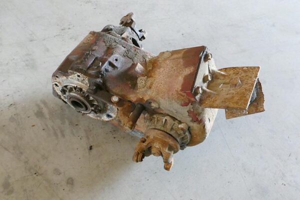
(NP205 Transfer Case)
NP231 Transfer Case
The NP231 is a compact, chain-driven, two-speed transfer case best known for its use in Jeep vehicles. It uses an aluminum housing and has a 2.72:1 low-range ratio.
The NP231 is a part-time transfer case and typically provides:
- 2WD High
- 4WD High
- Neutral
- 4WD Low
One of the important considerations when identifying or selecting an NP231 is the input configuration. Versions were produced with different input spline arrangements, including commonly encountered 21-spline and 23-spline configurations. The input shaft must match the transmission or an appropriate adapter must be used. An NP231 that fits one transmission may therefore not bolt directly to another transmission even though both transfer cases are identified as NP231s. The NP231’s compact size, simple design, aftermarket support, and availability of modifications have made it a popular transfer case for custom 4×4 projects.
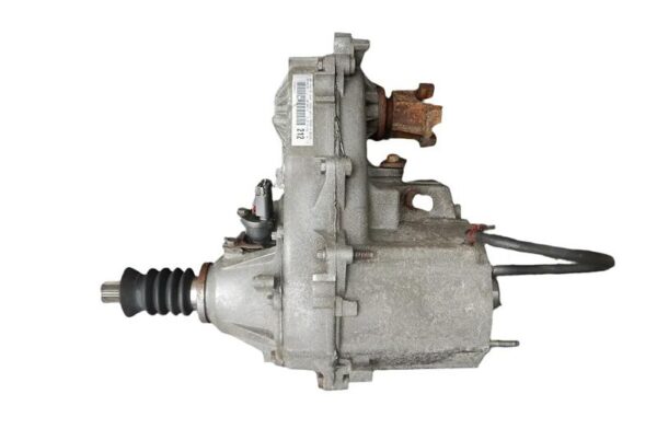
(NP231 Transfer Case)
NP242 Transfer Case
The NP242 is another chain-driven transfer case, but unlike the traditional part-time NP231, it provides both part-time and full-time four-wheel-drive operation.
Depending on the application, the available modes include:
- 2WD
- 4WD Full-Time
- 4WD Part-Time
- Neutral
- 4WD Low
The full-time mode allows the front and rear drivetrains to operate at different speeds, making it possible to use four-wheel drive on high-traction surfaces without the driveline bind associated with a conventional part-time transfer case. The NP242 is therefore a good example of why identifying a transfer case requires more than determining whether it is chain-driven. Two chain-driven transfer cases can have substantially different operating characteristics.
NP241 Transfer Case
The NP241 is a two-speed, chain-driven transfer case used in a variety of full-size truck and SUV applications. It is available in multiple configurations, with differences in input shafts, output arrangements, and vehicle-specific applications. The NP241 is generally considered a stronger design than the smaller NP231 and has been widely used in applications with larger engines and heavier vehicles. As with other New Process transfer cases, the specific version must be identified before assuming that it will mate to a particular transmission or drivetrain.
NP208 Transfer Case
The NP208 is a chain-driven, aluminum-housing transfer case used in numerous 1980s four-wheel-drive applications. It is a part-time two-speed case and can be found in different configurations depending on the manufacturer and vehicle. Because Ford, GM, and Dodge used versions of the NP208, the model number alone does not tell you everything about the case. The input, output, drop side, shift mechanism, and mounting configuration should be checked when identifying one for a swap.
NP203 Transfer Case
The NP203 is significantly different from the NP231, NP241, and NP208. It is a full-time four-wheel-drive transfer case that uses a center differential and was produced primarily for full-size trucks. Some versions incorporated a locking mechanism that allowed the center differential to be locked for part-time operation. The NP203 is also considerably larger and heavier than many later chain-driven transfer cases and is an example of an early full-time 4WD design.
NV271 and NV273 Transfer Cases
The NV271 and NV273 are larger, heavy-duty transfer cases used in later full-size truck applications. The NV271 is a manually shifted two-speed transfer case, while the NV273 uses an electronic shift system. Both were designed for heavy-duty applications and are substantially larger than light-duty cases such as the NP231. Their physical size, output configuration, input spline arrangement, and electronic or mechanical shift mechanism are important when considering them for a custom drivetrain.
Understanding New Process and New Venture Transfer Case Numbers
New Process Gear and New Venture Gear used a numbering system that provides useful information about many of their transfer cases. The system can help narrow down what a transfer case is and how it operates, but it should not be treated as a complete identification system.
New Process Gear later became New Venture Gear, which is why similar transfer cases may be identified with either an NP or NV prefix. A transfer case may also have a letter or other designation identifying the original vehicle manufacturer or a specific application.
For many NP/NV transfer cases, the three-digit model number can be interpreted as follows:
First Digit — Number of Speeds
The first digit identifies the number of available ranges or speeds in the transfer case.
- 1 = Single-speed
- 2 = Two-speed
A two-speed transfer case has both a high range and a low range. For example, the NP231 and NP205 are both two-speed transfer cases, while a model such as the NV136 is a single-speed unit.
Second Digit — General Case Strength
The second digit identifies the transfer case’s general strength or size class within the New Process/New Venture numbering system. The scale generally runs from smaller/light-duty designs toward larger/heavier-duty designs. For example:
- 3 = smaller/lighter-duty class
- 4 = larger/stronger class
- Higher numbers represent progressively heavier-duty designs within the system
This is a general classification, not a universal torque rating. The number should not be interpreted as meaning that every transfer case with a higher second digit is automatically stronger in every application. Actual strength depends on the specific design, shafts, gears, bearings, chain, housing, vehicle application, and other components.
Third Digit — Transfer Case Type
The third digit identifies the general operating and shifting configuration. Common designations include:
- 1 = Part-time 4WD
- 2 = Part-time/full-time combination, generally with manual shifting
- 3 = Part-time 4WD with electronic shifting
- 4 = Part-time/full-time combination with electronic shifting
- 5 = Special application/designation associated with certain Torsen-equipped systems
- 6 = Active on-demand system using an electronically controlled clutch
- 7 = Active on-demand system using a progressive-apply system
- 9 = Viscous-coupling system
The exact application and design should always be verified because the third digit describes the general transfer-case type rather than every feature of a particular unit.
Examples
The numbering system becomes easier to understand when looking at familiar transfer cases.
NP231 (The NP231 is a two-speed, chain-driven, part-time transfer case.)
- 2 = Two-speed
- 3 = General strength/size class
- 1 = Part-time 4WD
NV271 (The NV271 is a heavy-duty, two-speed, part-time transfer case used in full-size truck applications.)
- 2 = Two-speed
- 7 = Heavy-duty class
- 1 = Part-time 4WD
A transfer case being identified as an NP231, NP241, or NP205 does not automatically tell you which transmission it will bolt to or whether its outputs will work with a particular vehicle.
When selecting one for a drivetrain swap, identify the specific version of the transfer case, not just the basic model family.
BorgWarner Transfer Cases
BorgWarner has produced a large number of transfer cases for Ford and other vehicle manufacturers. Its transfer cases range from simple part-time 4WD units to electronically controlled full-time and all-wheel-drive systems.
Many BorgWarner transfer cases use aluminum housings and chain-driven front outputs, although the company has produced a wide variety of designs. The model number alone does not always identify the exact configuration, so the transfer-case tag and physical characteristics should be checked when identifying a specific unit.
BW1345 Transfer Case
The BW1345 is a chain-driven, part-time transfer case used in several Ford four-wheel-drive applications. It is a two-speed transfer case providing high and low range. Like other BorgWarner cases, different vehicle applications can have differences in input and output configurations.
BW1350 Transfer Case
The BW1350 is a three-piece aluminum, chain-driven, part-time transfer case used in Ford four-wheel-drive applications, including the Ford Ranger and Bronco II. The BW1350 was produced in both mechanical- and electronically shifted configurations and is found with different front-output arrangements depending on the application. The BW1350 and BW1354 are especially important to Ranger and Bronco II owners. For detailed information about their applications, identification, specifications, and differences, see our Ford Ranger & Bronco II Transfer Cases guide.
BW1354 Transfer Case
The BW1354 is another three-piece aluminum, chain-driven, part-time transfer case used in Ford light-duty four-wheel-drive applications. Like the BW1350, the BW1354 was available with different shift mechanisms and application-specific configurations. It is commonly associated with the Ford Ranger, Bronco II, and Explorer. See our Ford Ranger & Bronco II Transfer Cases guide. The specific output and input configuration should be verified when identifying a BW1354 or considering one for a drivetrain swap.
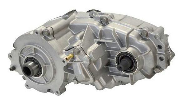
(BW1354 Transfer Case)
BW1356 Transfer Case
The BW1356 is a larger chain-driven transfer case used in heavier Ford truck applications. It is available in different configurations and was offered with both mechanical and electronic shifting depending on the application. Its larger physical size compared with the BW1350 and BW1354 is one of the characteristics that can help distinguish it when identifying an unknown BorgWarner transfer case.
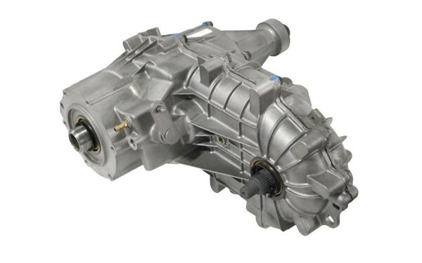
(BW1356 Transfer Case)
BW1359 Transfer Case
The BW1359 is another BorgWarner transfer case found in Ford applications. Its design and operating characteristics differ from the traditional part-time BW1350 and BW1354, making the model number and identification tag particularly important when determining exactly what version is being examined.
BW4404 Transfer Case
The BW4404 is a different type of BorgWarner transfer case from the traditional part-time Ranger units. It was designed for an all-wheel-drive (AWD) system and uses a viscous coupling to control torque distribution between the front and rear drivetrains. This illustrates why the term “BorgWarner transfer case” does not describe a single type of operating system. BorgWarner produced cases for part-time 4WD, full-time 4WD, and AWD applications.
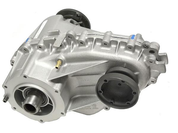
(BW4404 Transfer Case)
BW4405 Transfer Case
The BW4405 is an electronically controlled BorgWarner transfer case used in applications with a torque-on-demand four-wheel-drive system. Rather than mechanically locking the front and rear outputs together like a traditional part-time transfer case, the system uses an electronically controlled clutch to regulate torque transfer to the front drivetrain. The BW4405 is therefore an example of a transfer case that may look very different internally and operate very differently from the mechanically shifted BorgWarner cases used in older Ford trucks.
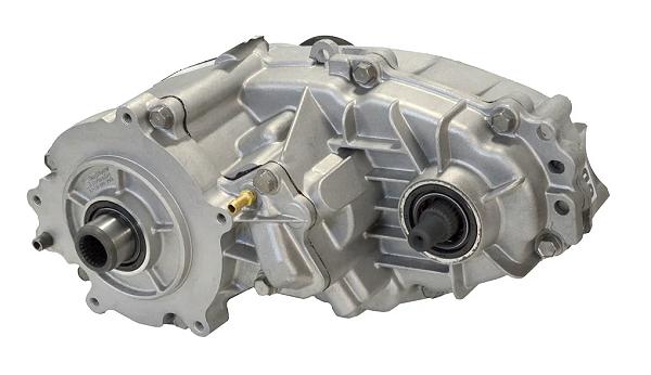
(BW4405 Transfer Case)
BW4406 Transfer Case
The BW4406 is a larger BorgWarner transfer case used in full-size Ford truck and SUV applications. It was produced in configurations for different drivetrain applications and may be found with electronic controls and different output arrangements. As with the other BorgWarner models, the exact vehicle application and transfer-case tag should be used to determine the specific configuration.
Dana and Spicer Transfer Cases
Dana/Spicer has produced some of the most recognizable gear-driven transfer cases used in four-wheel-drive vehicles. Many of the older Dana transfer cases use cast-iron housings and gear-driven front outputs, and several have become popular for restorations, drivetrain swaps, and custom off-road builds.
Dana 18 Transfer Case
The Dana 18 is an older, gear-driven transfer case used in Jeep and other early four-wheel-drive applications. It is recognizable by its compact cast-iron housing and gear-driven design. The Dana 18 uses a passenger-side front output, making the location of the front differential an important consideration when using one in a different vehicle. The Dana 18 was produced in several configurations over its long production run, so details such as the input shaft, gear ratios, and output arrangement can vary. Because of its age and simple gear-driven construction, the Dana 18 is commonly encountered in vintage 4×4 restorations and custom drivetrain projects.
Dana 20 Transfer Case
The Dana 20 is a two-speed, gear-driven transfer case used in a variety of Jeep, Ford, and other four-wheel-drive applications. It uses a cast-iron housing and is known for its compact design and durability. The Dana 20 has been particularly popular in classic Ford Bronco and Jeep applications and remains a common choice for vintage 4×4 restorations and custom builds. Different versions of the Dana 20 were produced for different vehicles. The input shaft, mounting pattern, front-output location, and output configuration therefore need to be checked when identifying a specific Dana 20. The Dana 20 is also commonly associated with twin-stick conversions, which allow the front and rear outputs to be controlled independently on appropriately modified cases.
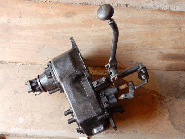
(Dana 20 Transfer Case)
Dana 300 Transfer Case
The Dana 300 is a compact, gear-driven, two-speed transfer case that was used primarily in Jeep applications. It uses a cast-iron housing and has become particularly popular with off-road builders because of its strong gear-driven design and extensive aftermarket support. The Dana 300 uses a passenger-side front output in its original configuration and provides a low-range reduction of approximately 2.62:1. Like the Dana 20, the Dana 300 can be modified with a twin-stick shifter, allowing the front and rear outputs to be controlled independently. It is also supported by aftermarket manufacturers offering upgraded gears, shafts, adapters, and other components.
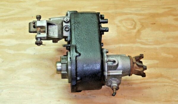
Gear-Driven Dana Cases and Custom Builds
The Dana 18, Dana 20, and Dana 300 illustrate why gear-driven transfer cases remain popular among custom 4×4 builders.
Their cast-iron housings, direct gear drive, relatively simple internal designs, and extensive aftermarket support make them attractive for applications where strength, serviceability, and modification potential are important.
However, a gear-driven case is not automatically stronger or better for every application. Transfer-case selection should also take into account:
- Engine torque
- Transmission compatibility
- Tire size
- Vehicle weight
- Intended use
- Front-output location
- Low-range ratio
- Driveshaft configuration
- Available adapters and aftermarket support
As with BorgWarner and New Process/New Venture transfer cases, the model number is only the starting point. The specific version of the case must be identified before assuming that it will work with a particular drivetrain.
Aftermarket Transfer Cases
Factory transfer cases are often used in custom 4×4 builds, but there are also transfer cases designed specifically for high-performance and custom applications. These aftermarket units can offer greater strength, multiple low-range ratios, different output configurations, and other features that make them easier to adapt to modified drivetrains.
Atlas II Transfer Case
The Atlas II, manufactured by Advance Adapters, is one of the best-known aftermarket transfer cases for custom 4×4 applications.
Unlike a factory transfer case designed around a specific vehicle and drivetrain, the Atlas II is available in a variety of configurations intended to make it easier to match the transfer case to a custom build.
Depending on the configuration, an Atlas II can be ordered with different:
- Input spline configurations
- Output configurations
- Low-range ratios
- Clocking options
- Shift arrangements
The Atlas II is also available in configurations designed for twin-stick operation, allowing the front and rear outputs to be controlled independently.
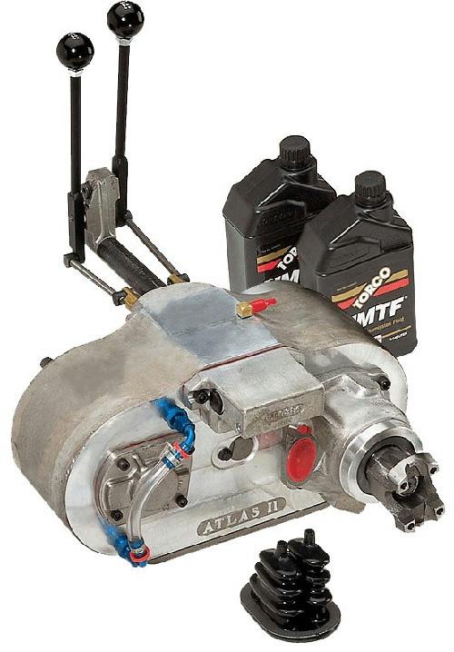
(Atlas II Transfer Case)
Transfer Case Anatomy & Mounting
Understanding the basic components of a transfer case makes identification easier and helps explain why transfer cases differ from one another. Although the internal design varies considerably between models, most transfer cases perform the same basic functions: they accept power from the transmission, provide high and low ranges on two-speed designs, and send power to the rear and front axles.
Input Shaft – The input shaft connects the transfer case to the transmission. Its spline count, diameter, length, and mounting arrangement vary between transfer cases and are critical when determining whether a transfer case can be used with a particular transmission. A transfer case may be designed to bolt directly to a specific transmission, or an adapter may be required to mate the two components.
Rear Output Shaft – The rear output shaft sends power toward the rear axle. Depending on the transfer-case design, the rear output may use a slip yoke, fixed yoke, or companion flange to connect to the rear driveshaft. The rear output configuration affects driveshaft design and can be an important consideration when installing a transfer case in a different vehicle.
Front Output Shaft – The front output shaft sends power to the front axle when four-wheel drive is engaged. Its location and connection vary considerably between transfer cases. The front output may be positioned on the driver or passenger side of the vehicle and may use a fixed yoke, slip-yoke connection, or flange. The front-output location is particularly important when selecting a transfer case for a swap because it must match the location of the front differential.
High-Range and Low-Range Gearing – Two-speed transfer cases provide both high range and low range. High range is used for normal four-wheel-drive operation. Low range uses additional reduction gearing to multiply torque at the wheels and reduce vehicle speed. This provides greater control and helps the vehicle overcome steep grades, obstacles, deep mud, rocks, and other conditions where additional wheel torque is needed. The low-range ratio varies between transfer cases. A transfer case with a 2.72:1 low range, for example, reduces the output speed to approximately 1/2.72 of the input speed while increasing the torque available at the transfer-case output.
Chain and Sprockets – In a chain-driven transfer case, a chain and sprockets transfer power from the mainshaft to the front output. The chain is contained inside the transfer-case housing and allows the front output to be positioned beside the mainshaft. Chain-driven designs are common in many light- and medium-duty transfer cases. Popular chain-driven transfer cases include the Borg-Warner BW1350, BW1354, and BW1356, as well as the New Process NP231 and NP241.
Gears – A gear-driven transfer case uses gears to transfer power to the front output. Depending on the design, gears may also be used for the high- and low-range reduction. The Dana 18, Dana 20, Dana 300, and NP205 are examples of well-known gear-driven transfer cases.
Planetary Gearset – Many two-speed transfer cases use a planetary gearset to provide low range. A planetary gearset consists of a sun gear, planet gears, a planet carrier, and a ring gear. The design and number of planetary gears can vary between transfer cases. Some BorgWarner transfer cases, for example, were produced with different planetary gear configurations during their production runs. The number of planets can therefore be an important specification when comparing different versions of the same basic transfer-case model.
Shift Mechanism – The shift mechanism controls the transfer case’s operating modes. Mechanical transfer cases typically use shift rails and shift forks to move internal components into the desired position. Other transfer cases use an electric shift motor or electronically controlled mechanisms. The external shift mechanism can provide a useful clue when identifying a transfer case and may also affect how easily it can be adapted to a custom vehicle.
Center Differential – Some full-time four-wheel-drive transfer cases contain a center differential. Unlike a traditional part-time transfer case that locks the front and rear outputs together, a center differential allows the two outputs to rotate at different speeds while still transferring power to both axles. This is what allows certain full-time 4WD systems to operate on high-traction surfaces without the driveline bind associated with a locked part-time system.
Viscous Coupling – Some transfer cases use a viscous coupling to control the difference in speed between the front and rear drivetrains. A viscous coupling contains a special fluid and internal plates. When there is a difference in rotational speed, the fluid’s resistance transfers torque between the plates. Viscous couplings were used in a number of full-time and all-wheel-drive systems and can be identified by the transfer-case design and application.
Electronically Controlled Clutch Systems – Some modern transfer cases use an electronically controlled clutch pack to regulate torque sent to one of the axles. Instead of mechanically locking the front and rear outputs together, the control system can vary the amount of torque transferred based on vehicle speed, wheel slip, throttle position, and other inputs. This design is common in torque-on-demand four-wheel-drive and all-wheel-drive systems.
Oil Pump – Some transfer cases use an internal oil pump to circulate lubricant through the case. The pump’s design and location vary by transfer case. For example, certain BorgWarner transfer cases use a positive-displacement oil pump driven by the rear output shaft. This type of pump arrangement can provide lubrication while the output shaft is rotating and is one of the distinctive internal features that can help differentiate transfer-case designs. The presence, location, and design of an oil pump can therefore be an important consideration when researching a transfer case for towing, a drivetrain swap, or a custom application.
Speed Sensors and Electronic Controls – Modern transfer cases may use electronic sensors and control systems to determine vehicle speed, transfer-case position, wheel slip, and torque distribution. When installing one in another vehicle, determine whether the transfer case can operate independently or requires communication with the vehicle’s computer systems. This can be an important consideration when swapping a modern drivetrain into an older vehicle.
Transfer Case Mounting
Married Transfer Case – A married transfer case bolts directly to the transmission and is the most common arrangement in modern 4×4 vehicles.
Divorced Transfer Case – A divorced transfer case is mounted separately from the transmission and receives power through a short driveshaft or intermediate shaft. A divorced transfer cases provide greater freedom in positioning the transfer case within the chassis, but they require additional mounting and driveshaft components.
Clocking and Clearance
The rotational position of the transfer case relative to the transmission is another consideration. Clocking changes the angle at which the transfer case sits in the vehicle. Changing the clocking can improve ground clearance or help position the transfer case for a particular chassis, but it can also create clearance problems with the transmission tunnel, floor, exhaust, crossmembers, or driveshafts. Some aftermarket transfer cases and adapters offer multiple clocking positions.
Transfer Case Modifications and Upgrades
Factory transfer cases can often be modified to better suit a custom 4×4. Common modifications include slip-yoke eliminator kits, twin-stick conversions, upgraded gears and shafts, output conversions, and transfer-case doublers.
The type of modification that makes sense depends on the transfer case, vehicle, suspension, tire size, and intended use.
Slip-Yoke Eliminator (SYE)
A slip-yoke eliminator (SYE) kit is a common modification for certain chain-driven transfer cases that use a rear slip yoke.
A conventional slip-yoke transfer case uses a long output shaft and tailhousing that allows the driveshaft to slide in and out as the suspension moves and the distance between the transfer case and axle changes.
An SYE kit replaces the original long output arrangement with a shorter output shaft and fixed yoke or flange. The driveshaft then incorporates a slip joint to accommodate changes in length.
An SYE can provide several advantages on a lifted vehicle:
- Allows a longer rear driveshaft
- Reduces rear driveshaft operating angles
- Can reduce driveline vibration
- Provides a stronger fixed output arrangement on some applications
- Keeps transfer-case lubricant from escaping through the tailhousing if the rear driveshaft is damaged
SYE kits are available for certain transfer cases, but they are not universal. The specific transfer-case model and version must be verified before selecting a kit.
Twin-Stick Conversions
Some gear-driven transfer cases can be modified with a twin-stick shifter. A conventional transfer-case shifter may control multiple internal shift rails through a single lever. A twin-stick conversion provides separate controls for the transfer case’s front- and rear-output functions on designs that allow the outputs to be controlled independently. Twin-stick conversions are commonly associated with transfer cases such as the Dana 20 and Dana 300. Depending on the transfer case and the modification, independent control can allow combinations that are not available with the factory shifter. Off-road drivers may use these configurations for specialized maneuvers such as front digs, where power is applied to the front axle while the vehicle pivots around it. Twin-stick operation is not appropriate for every transfer case, and some cases require internal modifications in addition to the external shifter.
Output Yoke and Flange Conversions
Transfer-case outputs can sometimes be modified to use a different type of driveshaft connection. A transfer case originally equipped with a slip-yoke or fixed-yoke output may be converted to a companion flange or other output configuration, depending on the available parts and the design of the case. These conversions can be useful when building custom driveshafts or adapting a transfer case to a different vehicle. The conversion must be matched to the transfer case’s output shaft, spline count, bearing arrangement, and available space. Simply changing the external yoke does not necessarily increase the strength of the entire transfer case or drivetrain.
Upgraded Gears and Shafts
Some transfer cases have aftermarket support for:
- Stronger output shafts
- Upgraded input shafts
- Lower low-range gears
- Stronger chains
- Upgraded bearings
- Reinforced housings
- Other internal improvements
These upgrades can allow a factory transfer case to survive applications beyond its original design. However, the transfer case is only one part of the drivetrain. Increasing its strength does not eliminate limitations elsewhere in the system. The transmission, driveshafts, U-joints, axles, differential gears, and other components must also be capable of handling the increased loads.
Transfer Case Doublers
A transfer-case doubler uses two transfer cases connected together to provide additional gear reduction. For more information on a transfer case doubler for your Ford Ranger or Bronco II, check out: Transfer Case Doubler Overview & FAQs
Transfer Case Diagrams
Check out this Catalog Of Transfer Case Parts & Diagrams for a breakdown of these and other transfer cases.
Related Articles
1983-2011 Ford Ranger Transfer Cases
Servicing A Transfer Case Shift Motor
Rebuilding A Transfer Case Shift Motor
BW1354 Transfer Case Exploded Parts View
Rebuilding A Ford Transfer Case Shift Motor
The 1983-2011 Ford Ranger 4WD System
Identifying Borg Warner Transfer Cases
Last Updated:
About The Author

Jim Oaks is the founder of TheRangerStation.com, the longest-running Ford Ranger resource online since 1999. With over 25 years of hands-on experience building and modifying Ford Rangers — including magazine-featured builds like Project Transformer — Jim has become one of the most trusted authorities in the Ford Ranger off-road and enthusiast space.
Since launching TheRangerStation.com, Jim has documented thousands of real-world Ranger builds, technical repairs, drivetrain swaps, suspension modifications, and off-road adventures contributed by owners worldwide. TheRangerStation.com has been referenced in print, video and online by enthusiasts, mechanics, and off-road builders looking for practical, and experience-based information.