
Introduction
This guide covers swapping a Ford Explorer 8.8-inch rear axle into a Ford Ranger.
It documents real-world installations, factory specifications, required modifications, and known pitfalls when upgrading from the stock Ford 7.5 or 28-spline 8.8 rear axle.
This swap is popular among 1983–2011 Ford Ranger owners building daily drivers, trail rigs, and overland trucks who want increased strength, factory disc brakes, and 31-spline axle shafts without changing wheel bolt pattern.
This guide is based on multiple Explorer 8.8 swaps performed by The Ranger Station staff and community members, combining factory data with real-world installation experience.
Why Swap an Explorer 8.8 Into a Ranger?
- 31-spline axle shafts (20–25% stronger than Ranger 8.8)
- Factory disc brakes on 1995+ Explorers
- Common 3.73 gearing with Traction-Lok limited slip
- Same 5×4.5 wheel bolt pattern as the Ranger
What’s Required for the Swap
- Spring perches welded to the top of the axle tubes
- Shock mounts welded in Ranger-compatible locations
- Correct driveshaft flange or adapter
- Optional axle tube welding for severe off-road use
Explorer 8.8 Swap Guide Contents
- Axle Size & Strength Comparisons
- Explorer 8.8 Specifications
- Spring Perch Removal & Installation
- Setting Pinion Angles
- Driveshaft & Flange Options
- The Explorer 8.8 Axle in my 1983 Ranger
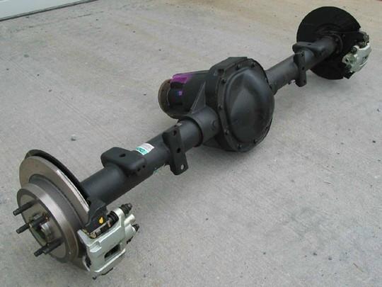
The Explorer 8.8
The Ford Explorer 8.8-Inch rear axle has found homes in numerous vehicles besides the Explorer. It has been swapped into Ford Rangers, Bronco II’s, Jeeps, Chevy S-10’s and even some cars.
The 8.8-Inch axle used in the Explorer is highly desirable because it came with 31-spline axles over the typical 28-spline found in the Ranger version. There’s a 20-25 percent difference in strength between this Explorer 8.8 and the Ranger 8.8. The bigger 31-spline axle accounts for most of that, but the 3.25-inch tubes also help. The 1991-1994 versions had 10-Inch drum brakes and the 1995 and newer models come with disc brakes.
Not all Ford Rangers came with 8.8-Inch rears. The base rear end in the Ranger has been the Ford 7.5-Inch. When Ford introduced the 4.0 V-6 into the Ranger in 1990, it came with a 8.8-Inch, 28-spline rear axle. The Ford 7.5-Inch axle was standard on the non 4.0 V-6 models.
Up until 2011, the Ranger could still be found with either the Ford 7.5 or 8.8 inch axles. The base model 8.8-inch axle is still a 28-spline, but the FX4’s come with a 31-spline 8.8-Inch rear axle.
The majority of these axles came with 3.73 gears and a Traction-Lok differential. The Traction-Lok can work very well and almost like a full locker if you apply a little brake pressure with your left foot while accelerating with the right.
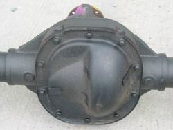
Ford 8.8 – Rear Cover
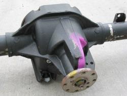
Ford 8.8 – Bottom (Diff is upside down)
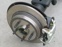
Ford 8.8 – Disc Brakes
Axle Comparisons
Here a list of how the Jeep Dana 35, Ford 7.5 and Ford Explorer 8.8 axles all measure up:
|
Measurement |
Jeep Dana 35 |
Ford 7.5-Inch (Ranger) |
Ford Ranger 8.8-Inch |
Ford Explorer 8.8-Inch |
|---|---|---|---|---|
| Width Between Wheel
Mounting Surfaces |
60-1/2″ | 56-1/2″
(1983-1992) 58-1/2″ (1993-2009) |
56-1/2″
(1990-1992) 58-1/2″ (1993-2009) |
59-1/2″ |
| Pinion Offset To Right Of Center | 3/4″ | ? | 2″ | 2″ |
| Pinion Length, Tube Center
To U-Joint Center |
11-1/2″ | 11-5/8″ | 11-5/8″ | 11-5/8″ |
| Pinion Height, U-Joint
Center Below Tube Center |
1-7/8″ | ? | 1-7/8″ | 1-7/8″ |
| Bottom Of Diff Housing
Below Tube Center |
5″ | 5 inches | 5-3/4″ | 5-3/4″ |
| Disc Brake Rotors | N/A | N/A | N/A | 11-1/4 x 7/16″ |
| Brake Drums | 9″ | 9 inches | ? | 10 inches |
| Drum brake shoes | 9 x 2-1/2″ | ? | ? | 7-1/4″ x 1-1/4″
(e-brake) |
| Distance between
spring perches (o/c) |
40-1/5″ | 38-1/2 inches | 38-1/2″ | 38-1/2″ |
| Tube diameter | 2-1/5″ | 2.80 inches
(1983-2009) 3-1/4 inches (2010-2011) |
2.80 ”
(1990-2009) (Non-FX4) 3-1/4 inches (FX4 Models) |
3.25 inches
(Neck Down To 2-3/4″) |
| Axle shaft diameter | 1.16″ 27-spline | 1.29″ 28-spline | 1.31″ 31-spline |
Replacing A Ford Ranger 7.5-Inch Axle With An Explorer 8.8-Inch Axle
Explorer 8.8 Facts
- Has 31-Spline Axle Shafts
- Beefier 3.25-Inch Axle Tubes
- 10-Inch Drums From 1990-1994
- 1995+ Have Disc Brakes
- Needs Shock Mounts Welded On
- Needs Spring Perches Welded To Top Of Axle Tube
- Most Have Limited-Slip (Traction Lok)
- Same 5×4.5 Wheel Bolt Pattern As Ranger
- Pre-1990 Ranger Driveshafts Will Not Bolt Directly Up To The Explorer 8.8 (Have Custom Shaft Made Or Get A 1990 Or Newer Shaft)
Explorer 8.8 Drawbacks
Rather than welding the tubes into the diff housing, the tubes are just held in with pressed-in plugs. These plugs tend to stop doing their job under severe stress, so you really should weld the tubes to the housing with low-hydrogen rod.

Photo Of Tube Welded To Center Section
The axle shafts are held in by C-clips. This requires opening and partially dismantling the differential in order to remove the shafts, and if you brake a shaft there’s nothing to hold your wheel onto the axle housing.
Brakes
The 1990-1994 Explorer 8.8-inch axle came with 10-inch drum brakes. 1995 and newer Explorers have disc brakes. People have reported that they have swapped in a newer disc brake 8.8-inch axle in place of their original drum brake axle without having to switch to a disc brake master cylinder.
Spring Pads – Removal


The Explorer axle mounts with the springs under the axle and the Ranger mounts in spring over configuration.
Removing the original spring and sway bar mounts from the axle tubes isn’t very difficult. You can use a 4.5″ angle grinder with cutting disks and a small sledge hammer. Use the grinder to cut about halfway through the weld beads and then beat on each end of the mounts with a hammer to finish breaking the weld beads and knock the mounts away from the axle tubes. Make sure you don’t cut in to the axle tube. If you cut in to the axle tube, it will have to be welded up to prevent it from becoming a weak spot in the tube.
Spring Pads – Install
The Explorer’s perch to perch distance is the same as the Ranger’s, but the new perch need to mount on the opposite side of the tube. Here the factory perches were left in place and new ones are being set in place on the other side of the tube.
The Rangers axle spring pads are spaced 38-1/2 inches from center to center with a 3/4-inch hole in the center for the blocks locating pin. You will need larger U-bolts to fit around the 8.8’s larger 3-1/4 inch axle tube.
If you were careful cutting off the factory spring pads, you can weld them back on the other side of the axle tube in the correct location. You can buy spring pads from most off-road shops.
The 8.8 is 3-1/4 inches in diameter and the Ranger uses a 2-1/2 inch wide spring pad. If you make your own out of 2-1/2 inch wide square tubing you’ll need to drill out a 3/4 inch hole in the center for the locating pin in the spring pack. Either way, make sure if you buy a pair of spring pads, they will fit a 3-1/4 inch axle tube and have a 2-1/2 inch wide pad.
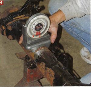
Pinion Angles
Setting the pinion angle is vital. Basically, the pinion angle is the degrees in which the axle pinion points up. There are two ways to do this. If you know the correct angle (in this case 6 degrees, i.e. the pinion was angled up six degrees from the level of the spring perch), you can level the pinion and simply set the perch at six degrees using a dial protractor (cheap and available at Sears or other tool stores) and weld it into place. The other way is to actually install the axle with the perches loose and the U-bolts not fully tightened. Center the axle on the springs, hook up the driveshaft, rotate the axle inside the U-bolts until you get the right driveshaft and pinion angles, tack-weld the perches in place then remove the axle to do the final welds. This latter method also works with determining shock mount locations.
For more information on pinion angles, go to the ‘Checking Pinion Angles’ page. I wanted to set up the new axle before I removed the old one. I contacted Ford Motorsports at 1-810-468-1356 and asked them what the pinion angle would be for an 8.8 in a long bed 4×4 Ranger with a standard cab and automatic transmission. They told me 6-degrees and that’s what I had the new spring pads welded at. This has worked out great for me. Be careful when measuring pinion angle on Rangers with lift kits installed. My 4-Inch lift uses tapered rear blocks which affects the pinion angle. If you have a kit installed, you should remove the rear end, place a level on the pads and make the rear end level, and then check the pinion angle at the flange.
Check Out: Pinion & U-Joint Angles
Shock Mounts
The Explorer shocks mount in a different location than those on a Ranger.
You’ll have to have new shock mounts welded on and can buy them from an off-road shop. I had the shock mounts welded on at 40-degrees. The mounts were welded on with a 3-3/4 inch space between them and the spring pads.
Driveshaft
If swapping this axle into another vehicle, one thing to note is that the 8.8 uses a pinion flange instead of a pinion yoke like most Dana axles. Spicer makes adapters called flange yokes that connect this flange to larger 1330-style U-joints or smaller 1310-style U-joints. The 1310 yoke is Spicer part number 2-2-1379. The 1330 yoke is P/N 2-2-1369. The stock Explorer driveshaft uses a 1330 joint, so you can grab the adapter from your axle donor if that’s the size you need. These adapters bolt to the pinion flange with 12mm x 1.75 thread bolts. The 12-point factory bolts are Ford P/N N800594-S100.
I was told that the driveshaft from a 1990 or newer Ranger will bolt right up to the 8.8. My 1983 Ranger used the small 2-1/2 inch wide u-joint and 2-inch shaft. The Rangers flange had a 2-1/2 inch spacing between bolt holes and the Explorer flange had a 3-inch spacing between bolt holes.
My driveshaft wouldn’t bolt to the new 8.8’s flange, so I decided to have a new driveshaft built. I could have found a flange for the 8.8 that would accept the 2-1/2 inch u-joint in order to retain my original shaft, but I wanted to beef things up a bit. I went to Henderson Driveline & Axle in Westlake, Ohio and had them build a larger 2-1/2 inch driveshaft to replace the existing 2-inch shaft.
We came up with a dual flange 1310 setup for the driveshaft. The shaft was built with 1310 u-joints at each end and a flange that attaches to the flange on the axle and the flange on the transfer case. I got rid of the yoke on the transfer case and replaced it with a flat flange from a 1986 Bronco II transfer case. These flat flanges allow the bigger u-joints and eliminate the weak u-joint straps at the transfer case.
The Explorer 8.8 Axle in my 1983 Ranger
My axle came from a 1994 Explorer and has 3.73’s and a Traction-Lok. I paid $400.00 for it and it came with 3.73’s and a Traction-Lok.
You can find out what gears are in it by reading the axle tags or door codes. Check out the Rear Axle Page for more information on identifying 8.8’s. I pulled the axle shafts and verified that they were 31-splines since I didn’t actually see it come out of the Explorer. I didn’t want to end of with a 28-spline Ranger version.
In 1995 the axles came with disk brakes. My axle still had the drums; however, they’re an inch larger in diameter than the 7.5’s with much bigger brake shoes. I completely stripped all of the brake components from the backing plates and started with all new parts. For some dumb reason my 8.8 came with a plastic inspection cover, so I replaced it with a heavy-duty cover from TRS Fab & Off-Road (James Oaks Enterprises LLC)
Here’s a few photos. Sorry for the poor quality
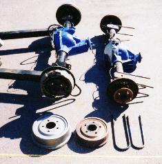
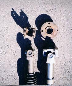
Here is a side view of the 8.8 to the left and 7.5 to the right.
Notice the size difference between the brake drum’s and U-bolt’s.
If you look closely in this photo, you’ll notice that the flanges (right) on the ends of the axles are different sizes.
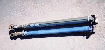
Here is a photo of the new shaft in front of the old one. Note the different flange used with the new one and the strong u-joint setup. The old setup in the rear uses a weak u-joint strap setup. The yoke (rear shaft) if the stock yoke from my transfer case. The flange (front shaft) is from the Bronco II transfer case.
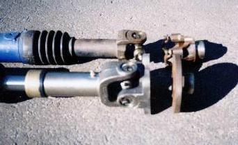
This is a look down at the new flange on the right compared to the old setup on the left. Note the larger u-joint, flange and shaft.
The Explorer 8.8 Axle in my 1996 Ranger
I again found myself installing an Explorer 8.8-Inch axle in a Ranger in 2004.
This time I was building up a 1996 Ford Ranger Extended Cab that had a 4.0 V-6 and 28-spline rear axle. Since I was building a solid trail rig with new gears and Detroit Lockers, I decided to go ahead and beef up the rear end with a 31-spline Ford 8.8 with disc brakes.
This time around I was able to use the original Ranger driveshaft for a direct bolt in. After about a week, I decided to swap in a 1-piece shaft from a newer extended cab Ranger. Extended cab Rangers up to 1997 had a 2-piece driveshaft. 1998 and newer extended cab Rangers have a 1-piece driveshaft. For more information, click HERE.
The Explorer axle mounts with the springs under the axle and the Ranger mounts in spring over configuration. The shocks also mount in different locations. After torching or cutting off all unnecessary brackets, I used a grinder to clean off the area where the new spring perch would be welded to the tube.
The Explorer’s perch to perch distance was the same as the Ranger’s, but the new perch needed to mount on the opposite side of the tube. I left the old perch in place. Setting the pinion angle is vital to getting a vibration-free driveshaft. There are two ways to do this. If you know the correct angle (in this case 6 degrees, i.e. the pinion was angled up six degrees from the level of the spring perch), you can level the pinion and simply set the perch at six degrees using a dial protractor (cheap and available at Sears or other tool stores) and weld it into place. The other way is to actually install the axle with the perches loose and the U-bolts not fully tightened. Center the axle on the springs, hook up the driveshaft, rotate the axle inside the U-bolts until you get the right driveshaft and pinion angles, tack-weld the perches in place then remove the axle to do the final welds. This latter method also works with determining shock mount locations.
Welding the perches and the shock mounts must be carefully done so as not to overheat the tube and possibly distort it. The best way to do that is to weld about an inch at a time, let it cool then weld another inch on the opposite side and let it cool again. Repeat this until you have it fully welded.
The new axle bolts up just like the old one, though you will need new 3.25 U-bolts and spring plates to replace the Explorer’s 3-inch pieces. The shock mounts were welded on after the axle was installed so as to get the correct position. The brakes were installed after the axle was installed using new or rebuilt parts from a local auto parts store.

Common Explorer 8.8 Swap Questions
Is the Explorer 8.8 a direct bolt-in for a Ranger?
No. While the axle width and bolt pattern are compatible, spring perches and shock mounts must be relocated and welded.
Which Explorer years are best for this swap?
1995–2001 Explorers are the most desirable due to factory disc brakes and common 31-spline axle shafts.
Will my Ranger driveshaft fit an Explorer 8.8?
Some 1990+ Ranger driveshafts bolt up directly, but earlier trucks often require a flange adapter or custom shaft.
Related Articles
Ford Ranger Rear Axles (1983-2011)
Ranger / Bronco II 7.5-Inch Axle History & Specs
Ranger / Explorer 8.8-Inch Axle History & Specs
Explorer 8.8-Inch Swap – No Welding
How To Spot A 31-Spline FX4 8.8-Inch Axle
What Is A Torsen Limited Slip Differential
About The Author
Jim Oaks is the founder of TheRangerStation.com, the longest-running Ford Ranger resource online since 1999. With over 25 years of hands-on experience building and modifying Ford Rangers — including magazine-featured builds like Project Transformer — Jim has become one of the most trusted authorities in the Ford Ranger off-road and enthusiast space.
Since launching TheRangerStation.com, Jim has documented thousands of real-world Ranger builds, technical repairs, drivetrain swaps, suspension modifications, and off-road adventures contributed by owners worldwide. TheRangerStation.com has been referenced in print, video and online by enthusiasts, mechanics, and off-road builders looking for practical, and experience-based information.