
1996 Ford Ranger ~ 2.3L Engine Evaporative Purge System Check Engine Code = P1443
By: Tomshints.com
Note: I wrote this article after being exasperated trying to find information about this purge system. I hope this article saves someone my frustrations. (For those of you that think this article is too detailed: it’s not for you, but for the guy without your vast knowledge.)
Let’s start by understanding the two principle components …
The Purge Solenoid:
- This device is really an electrically operated valve. A “Solenoid” is just a coil of wire wound around a movable metal core.
- In this application it is a valve that allows opening or closing the vacuum line between the charcoal canister and the vacuum pick-up near the throttle body.
- The solenoid is supplied 12-Volts when the key is on.
- The computer switches the ground return path to activate the valve. This valve is closed when no current is applied.
- Usually these type of valves are direction-of-flow sensitive, so be mindful of orientation.
- A simple test is to try blowing through the valve with no current applied: the valve should be closed.
- Now apply voltage to the terminals from a 12-Volt battery.
- These devices are not diode protected so polarity does not matter.
- With voltage applied you should be able to blow through the valve.
- This test is not very quantitative but usually suffices. A more thorough test is described later in the article.
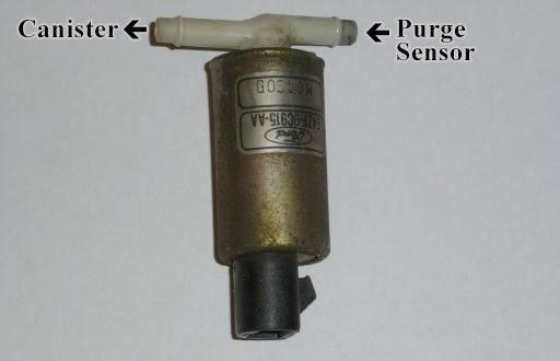
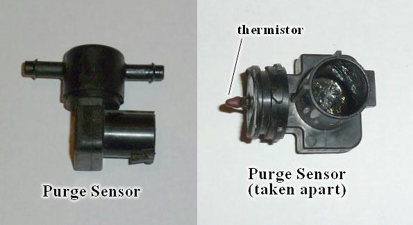
The Purge Sensor:
- This is a sensor!!!
- This seems to be a completely misunderstood device. I see many references on the web calling it a solenoid. Even O’Reilly Auto Parts called it a “Canister Purge Solenoid” (but they do carry it – part number CP509 @ $23.99). And a parts-store clerk became argumentative when I said “It is not a solenoid”.
- It is a thermistor in a small chamber that air flows over. A thermistor is a temperature sensitive resistor typically having a negative temperature coefficient.
- This device allows the computer to tell when air is being drawn from the charcoal canister to the vacuum intake near the throttle body.
- A test sequence is given later in the article.
- Orientation probably doesn’t matter.
Evaporative Purge System component routing
NOTE: I have not dealt with the line back to the gas tank or the valving on the gas tank because my problem was not there.
- There is a vacuum tap by the throttle body.
- A hose goes from the vacuum tap to the purge sensor.
- A hose goes from the purge sensor to the purge solenoid.
- A hose goes from the purge solenoid to the charcoal canister.
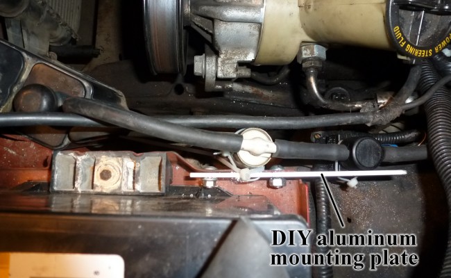
I was not happy with Ford’s way of hanging the devices so I attached a piece of aluminum to some existing holes in the battery tray for mounting them properly.
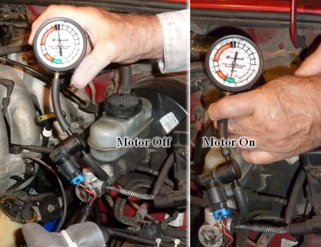
Test 1 – Check that the vacuum hose is not broken or plugged
- Put a vacuum gauge directly on the hose that comes from the vacuum tap near the throttle body.
- Start the motor: the vacuum should read about 20 Inches of Mercury.
- This value is not critical to the purge system but shows that the hose from the vacuum intake is not broken or plugged.
Test 2 – Check that the purge sensor is not plugged
- Remove the hose between the purge flow sensor and the purge solenoid at the purge solenoid end.
- Put a vacuum gauge on the end of the hose you removed from the purge solenoid.
- Start the motor… the vacuum should read about 20 inches.
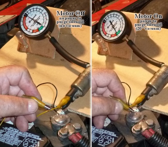
Test 3 – Check the purge solenoid
- Remove the hose between the purge solenoid and the charcoal canister, at the canister end. Put a vacuum gauge on the hose removed from the canister.
- Unplug the electrical connector from the purge solenoid.
- Attach a clip lead from one pin of the purge solenoid to ground on the battery.
- Attach another clip to the other pin of the purge solenoid, do not connect the other end at this time. It does not matter which lead goes to which pin since the solenoid is not diode protected.
- Now start the vehicle.
- Since the purge solenoid should be closed when no current is applied, the vacuum gauge should read zero.
- With engine still running, touch the unattached lead to the positive pin of the battery: the vacuum should jump up to approximately 20 inches.
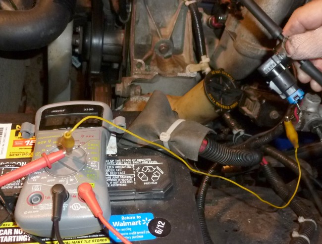
Test 4 – Check that voltage is being supplied to the purge solenoid
- NOTE: The computer controls the purge solenoid using the ground return.
- Disconnect the purge solenoid connector.
- Set your multimeter to a DC-Voltage scale capable of reading 12-Volts.
- Using a clip lead, connect the negative meter lead to the negative terminal of the battery.
- Look at the back of the purge solenoid connector to check which pin connects to the red lead.
- Turn on the key and using the positive lead of the meter, see if about 12-Volts is present on the red lead’s pin (the voltage is not critical as long as is somewhere around 12-Volts).
- If the voltage is not present, there is a problem, but it is beyond the scope of this article.
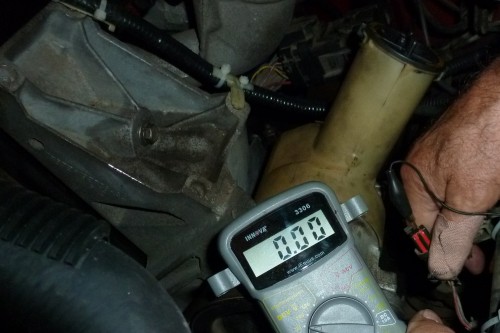
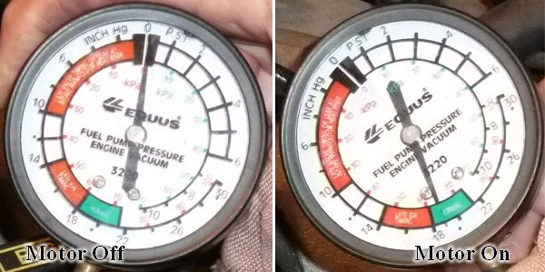
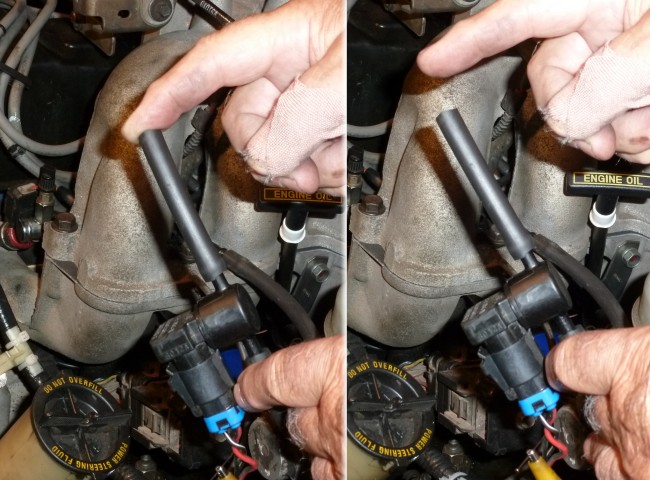
Key off… no supply voltage to purge solenoid.
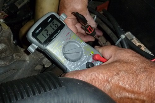
Key on… supplies voltage to purge solenoid.
Test 5 – Check that the purge flow sensor is working
- What we are trying to do is draw air through the purge flow sensor and see if its thermistor in functioning. Our goal is to be able to monitor the voltage on the purge flow sensor signal lead.
- Remove the hose between the purge solenoid and the purge flow sensor.
- Set up your multimeter to a DC-Voltage scale capable of reading 12-Volts.
- Using a clip lead connect the negative meter lead to the negative terminal of the battery.
- Now get a couple of straight pins or needles since it may take more than one for the next operation.
- The idea is to pierce the insulation of the signal lead allowing signal voltage monitoring (If you haven’t tried piercing a wire before I suggest you hold the pin in nose pliers and put a small piece of wood below the wire).
- The signal lead is the black lead with a light green stripe.
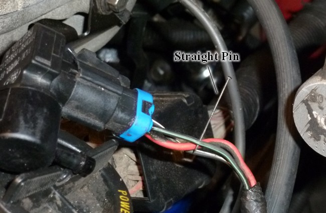
- Hook the positive lead of the meter to the pin.
- Now start the vehicle.
- You should be able to cycle the reading from the purge flow sensor by alternately putting your finger over the end of the hose and removing it.
- The bad sensor read about 1.23-Volts with my finger on the hose and about 1.45-Volts with the line open.
- With a new sensor I read about 1.65-Volts with my finger on the hose and about 3.57-Volts with the line open.
- Full response was a couple of seconds.