
Ford 2.9L to 5.0L EFI Engine Swap Wiring Guide (Ranger & Bronco II)
This article documents the electrical and wiring portion of a Ford 2.9L V6 to 5.0L EFI V8 engine swap performed on a 1986 Ford Bronco II using a Lincoln Town Car 5.0L EFI drivetrain. While this guide is based on that specific swap, the wiring principles and connections apply to Ford Rangers and Bronco IIs originally equipped with the 2.9L V6.
This is a wiring-focused guide. It assumes the engine is already installed and positioned correctly and does not cover motor mounts, exhaust fabrication, cooling system changes, transmission selection, or drivetrain modifications. The goal of this article is to clearly explain how to integrate the Ford 5.0L EFI engine harness and computer into the existing Ranger/Bronco II chassis wiring so the engine starts, runs, charges, and communicates with the vehicle correctly.
Topics covered include:
- Integrating the 5.0L EFI engine harness into the Ranger/Bronco II electrical system
- Fuel pump relay and inertia switch wiring
- Ignition start/run circuits
- Grounding requirements and common failure points
- Check engine light, oil pressure, and starter signal wiring
- Vehicle Speed Sensor (VSS) considerations for EFI operation
This guide is intended for enthusiasts performing a 2.9 to 5.0 engine swap who want a reliable, factory-style wiring solution using OEM Ford components.
Wiring The Ford 5.0L
By ‘Dishtowel’
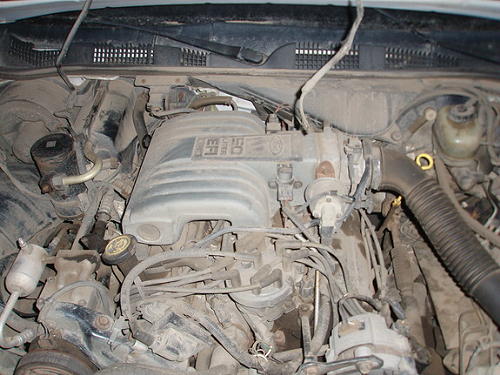
The Lincoln’s (Ford) 5.0L V-8
This wiring guide is derived from my experience installing a Ford 5.0L EFI engine from a Lincoln Town Car into a 1986 Ford Bronco II that had a 2.9L V-6. That is what this specifically applies to, but I believe that it will work with any Ranger or Bronco II that had the 2.9L.
Alternator Harness
The Ranger/Bronco II alternator harness will plug straight into the 5.0L alternator and successfully charge your system.
Injector Harness & Main Computer Harness
When doing this conversion, you will need the small injector harness and the main computer harness that came with the 5.0L.
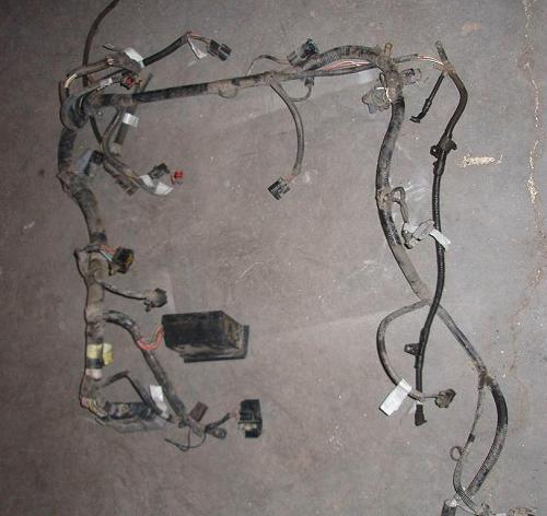
(5.0L Main Harness)
Once you have installed the engine and are happy with its position and have installed the harness from the car you are ready to button up wiring.
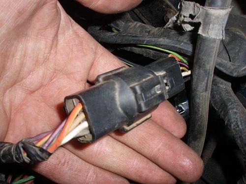
Black Square, 16-Pin Connector
Not far from the computer connector is a Black Square, 16-pin connector:
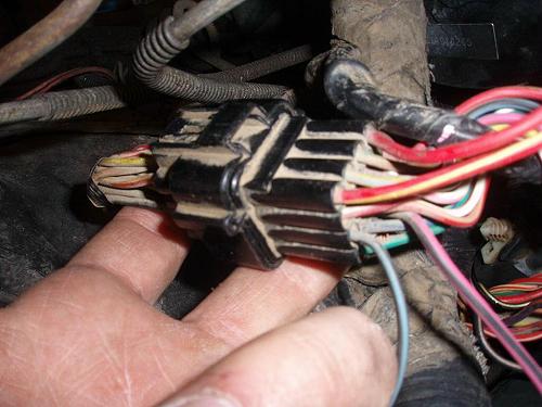
(Black Square 16-Pin Connector)
1) Red/Yellow = Control to fuel pump relay. Must go through the Ranger/Bronco II inertia switch and connect to Solid Red (#4). The inertia switch is by the passenger left foot; it has Pink/Black & Orange/Blue wires. It’s connector in the engine bay is a Black Rectangular 2-Pin. (Inertia switch connector pictured)
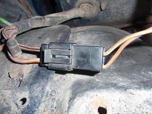
(Inertia Switch Connector)
2) Yellow/Blue = Vehicle speed sensor for cruise control, not used.
3) Tan/Green = VIP (?) connection, not used.
4) Red = Connect to #1 wire (Red/Yellow) through the inertia switch.
5) Red/White = Unknown, not used.
6) Pink/White = Unknown, not used.
7) Pink/Purple = VIP (?) feed, not used.
8) White/Red = Oil pressure warning light.
9) Black + 2 Blue Stripes = GROUND
10) Tan/Red = Check engine light
11) Blue + 2 Black Stripes = Speed Control sensor, not used.
12) Red/Dark Green = This wire is HOT when starting, (resultant). Not used.
13) Green/Orange = Cruise control, not used.
14) Blue/Green = This wire went to the instrument panel, not used.
15) Pink/Black = Big power from fuel pump relay to Ranger/Bronco II harness and into Ranger/Bronco II fuel pump. Connect to Orange/Black wire that goes into Black/Grey/White Round 1-Pin connector. (Connector pictured below)

(Black/Grey/White Round 1- Pin Connector)
16) Green/White = Anti-Lock brakes, unused
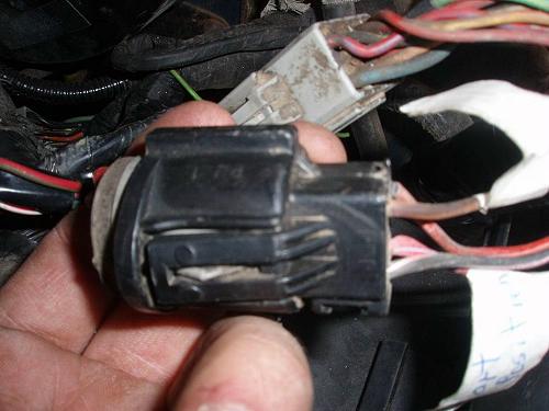
Black Round/Rectangular 8-Pin, 7-Wire Connector
On the 5.0L harness there is a Black Round/Rectangular 8-pin, 7-wire connector:
(Black Round/Rectangular 8-Pin, 7-Wire Connector)
1) Black = Connect to a big fat Red wire from a Grey Rectangular 8-pin connector on the Ranger/Bronco II.
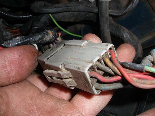
(Grey Rectangular 8-Pin Connector)
2) White/Pink = Connect to Red/Light Blue (Start position on Key) from Black/Grey Round 4-pin connector on Ranger/Bronco II. (Pictured)
(Black/Grey Round 4-Pin Connector)
3) Tan/Yellow = Unknown, not used.
4) Orange/Yellow = Connect to Purple/Orange (Run position on key) from Black/Grey Round 4 pin connector on Ranger/Bronco II.
5) Purple = MAF sensor to EEC (not used because I used a Speed Density motor/computer combo)
6) Red/Yellow = Unknown, not used.
7) Black/Pink = Unknown, not used.
Black Round 4-Pin Connector
At the opposite end of the harness from the computer there a Black Round 4-pin connector.
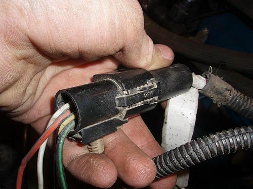
(Black Round 4-Pin Connector)
1) Black/Green = GROUND
2) Orange/Blue = Always hot, 20 Amp fuse.
3) Yellow/Black = Always hot, 30 Amp fuse.
4) White/Blue = Starter Solenoid/Relay signal wire. This is the wire that tells your starter to engage.
There is a two-pin connector that splices out of the Neutral Safety Switch loom down with the transmission. This goes to your vehicle speed sensor, which is piggy-backed on your speed-O gear. This just transmits a frequency, so which-wire-to-which-wire does not matter. I just cut into my existing wires going from the VSS to the 2.9 computer and attached them to the wires going to the 2-pin connector. This tells the computer that the vehicle is in fact moving. You can run without this hooked up, but it may lead to stalling when you snap the throttle closed under load, or coming to a stop with an automatic.
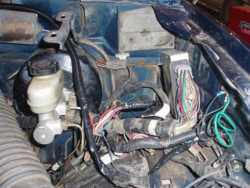
I was able to tidy all my wiring into one neat corner with the computer. I have yet to secure (and hopefully make water resistant) the computer yet, but that is about where mine will live. I ran the 60 pin, relay box, and the other connecter in-between the brake master cylinder and above the brake lines coming from it.
Other Notes
- MAKE SURE TO WELL GROUND ALL GROUND WIRES, THIS IS THE MOST LIKELY CAUSE OF FAILURE.
- Make sure Grey/Light Blue on the 60-pin computer connector is well grounded.
- Make sure you have good connection on your 60-pin connector. I suffered from an erratic computer my first week because not all pins were making contact. My ohm meter pin is slightly bigger than the female side of the connector and they were all stretched a tiny bit. I went in and crimped them with O-ring pliers. 100% now.
- This answer key is derived assuming you have a working and plugged in Neutral Safety Switch. The start signal goes from the key through the NSS, then to the starter. Do not hotwire the NSS this is one of the most dangerous things you could do. Especially if someone besides you ever has to drive this vehicle. (Which will eventually happen.)
Last Updated:
About The Author
Jim Oaks is the founder of TheRangerStation.com, the longest-running Ford Ranger resource online since 1999. With over 25 years of hands-on experience building and modifying Ford Rangers — including magazine-featured builds like Project Transformer — Jim has become one of the most trusted authorities in the Ford Ranger off-road and enthusiast space.
Since launching TheRangerStation.com, Jim has documented thousands of real-world Ranger builds, technical repairs, drivetrain swaps, suspension modifications, and off-road adventures contributed by owners worldwide. TheRangerStation.com has been referenced in print, video and online by enthusiasts, mechanics, and off-road builders looking for practical, and experience-based information.