
Introduction
Dallas Wiebe (2caseB2) shows that you can build a dual transfer case (doubler) setup for your 1983-2011 Ford Ranger 4×4 using mostly stock parts.
Overview
It is not an impossible thing to build your own dual transfer case setup using mostly stock parts. I started with a BW1354 electric case that I got from the wrecking yard as a core for $60.00. I put this custom case between a C5 automatic transmission and a BW1350 transfer case. The transmission and the rear transfer case were unmodified except for a sharp elbow on the transfer case vent and a slight notch in the transfer case adapter to clear the doubler (the reduction unit you will be building) shifter cable. The transmission and dual case assembly ended up being only 1-1/2″ longer then my original A4LD – BW1350 setup, although it still requires driveshaft length changes.

Now To Build The Doubler (The Reduction Box)
I started by splitting the core case at the factory split down the middle. You want to keep the front half (with the planetary and low range shift fork). The chain, the rear case half and all the 4wd shifter mechanism isn’t needed. The factory split point on the rear of the front case half is of course nice and square, we need to adapt this to the front of the stock rear case.
I sawed off extra chain case area of the front case half, leaving enough area to work a shifter fork and a cable engage mechanism. I used 1/2″ aluminum plate to enclose the chain area and make the back of the doubler.

The bolts that hold the front of the transfer case bearing retainer (the factory adapter plate) to the case body must be removed and drilled all the way through the case and the rear 1/2″ plate (which needs a very round hole in the middle which fits snuggly on to the front of the rear transfer case). A long ready rod (threaded rod / all thread) goes through the whole thing and threads into the bolt holes of the bearing retainer (factory adapter plate) of the rear transfer case. Each of the four rods have two nuts, one at the front of the doubler bearing retainer and one at the front of the rear case bearing retainer.

These four rods and one bolt inside, near the shifter fork area where the chain used to run, holds the doubler together and holds it to the rear transfer case.
I got the machine shop to build the doubler output shaft by joining an old 4WD transmission output shaft to the front section of the original doubler main shaft.

The shaft was made by boring the doubler stub out and using 50 tons of pressure to press the machined trans output shaft into the middle. Using the custom doubler output shaft for alignment I stacked the doubler on the rear (main) transfer case with the 1/2″ adapter plate between. The adapter plate was already drilled for the ready rod, the alignment dowel pin, and had a well-fitting 4-1/8″ hole in the middle (hole saw a die grinder and lots of patience). With these pieces all aligned I welded the doubler to the adapter plate. Yes, you can put all the doubler guts in from the front.
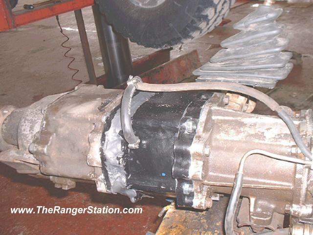
After welding plates over the opening in the side where the chain used to run, I had a basic case built.
Note- I am not a professional aluminum welder, but I had a very hard time getting a good bead between the cast aluminum case and the aluminum plate. I am told this is because of the very high magnesium content in the cast case.
Shifting This Beast
The rail that the shifter fork rides on must be shortened and a hole must be drilled in, but not through, the rear 1/2″ adapter plate. The shifter fork was modified to accept the end of a vacuum operated shifter cable as used in a Chevy S-10 front differential lock.

A hole was drilled in the front of the doubler, and a fitting was tapped and sealed into place which would accept the S-10 cable housing. A spring, which used to be on the other side of the shift fork, was placed between the front inside of the doubler and the shifter fork. The fork was ground down a little, so the spring goes over the area where the shifter rail goes through the fork. The spring of course moves the shifter fork in the opposing direction of the vacuum cable. The vacuum pot was screwed to the firewall and is operated by an EGR vacuum solenoid used in carbureted operated Rangers and the like. The rear case shifter will have to be secured to the side of the doubler and modified to reach your stock shifter hole (If you use the A4LD 4×4 shifter your only 1-1/2 inches short).

There is lots more little stuff to it, like drain and fill plugs, a vent, and actually getting the dang thing to hold oil. But if you’re into this kind of fabrication these things are fairly obvious to figure out.
Update 05/11/2002 – From 2caseB2
The shaft between the two cases which was made from two pieces pressed together snapped. Shaft needs to be made of one piece.
Update 07/16/2002 – From 2caseB2
The input shaft for the dual transfer case did break, I just welded the stub onto the input of the second transfer case. It is stronger than before and is still working, but if the input bearing of the second case ever goes, I’m screwed because the shaft I welded on is bigger than the id. of the bearing. The machine shop wanted over $500 to make a hardened shaft from scratch with no warranty, so for that price I can buy ten transfer case input bearing assemblies. So, it is still working great, but it is not in the bolt on department in any way shape or form. Bottom line, hard to make, marginal strength, leaks a little oil, AND ROCK CRAWLS LIKE NO TOMORROW!!
To spline the shaft would be a good idea, but they are actually hollow, once the shaft was machined to the correct diameter it would be very thin wall. Interesting point is that the shaft didn’t break back into the two pieces but instead broke just where the spline on the small part of the shaft ended. The actual press fit between the two pieces didn’t slip.
Related Articles:
Transfer Case Doubler Overview & FAQ’s
1983-2011 Ford Ranger Transfer Cases
BW1354 Transfer Case Exploded Parts Diagram
D&D Transfer Case Doubler Install
Building a BW1350-1354 Transfer Case Doubler
Co-Author
Thank you to TRS forum member Dallas Wiebe (2caseB2) for sharing his practical experience building this doubler and providing the information to the author to publish at The Ranger Station for other Ford Ranger owners to use.
Last Updated:
About The Author
Jim Oaks is the founder of TheRangerStation.com, the longest-running Ford Ranger resource online since 1999. With over 25 years of hands-on experience building and modifying Ford Rangers — including magazine-featured builds like Project Transformer — Jim has become one of the most trusted authorities in the Ford Ranger off-road and enthusiast space.
Since launching TheRangerStation.com, Jim has documented thousands of real-world Ranger builds, technical repairs, drivetrain swaps, suspension modifications, and off-road adventures contributed by owners worldwide. TheRangerStation.com has been referenced in print, video and online by enthusiasts, mechanics, and off-road builders looking for practical, and experience-based information.