
Introduction
This article you are about to read describes in general what it takes to design your own lift brackets, or any bracket for that matter. The way I will describe it will be the way the automotive industry will develop parts for your vehicle. The aftermarket companies that build your lift kits will also use this method of prototyping parts for the lift. I did all my designing on the computer using a CAD program called “Unigraphics”. I use this program where I work so whipping off the design is a walk in the park with this program.
Let’s Get Started
To start with I was able to get a hold of the factory drop brackets for the front beams. I then proceeded to dimension the part on a rough sketch on paper. I do this type of work for a living so naturally I know what dimensions and how to best utilize the measurement I have taken to produce the part in the computer. I used the Modeling feature to create the part in 3D full size. From here I have a base line model of the part to start working with. The brackets I designed are for a 4″ lift, but I also have incorporated a 3″ lift into the bracket, by adding another hole for the pivot.
With the base brackets modeled, I then went to my truck and measured some key locations to find out where and how the brackets are oriented on the frame. I now can place the brackets in relation to the ground and each other. The way they will be on the truck. With that established, I can then proceed to relocate the pivot holes 4″ down from where the factory holes are. Now that I know where the holes are I can then redesign the bracket around those key points. Most of the economy-lift kits use a plate to drop the passenger beam down and retain the factory cast bracket. The problem with this bracket is that some are poorly supported and they have a problem of putting a hole in the front differential when getting the front of truck, a bit airborne. I chose to incorporate the design of the factory bracket and the drop plate into one bracket and give the diff adequate clearance. There are a few manufactures that use this method for this bracket in particular, Skyjacker and James Duff to name a few of the major players to do so.


With the help of a few friends, I was able to figure out a compact, simple, yet effective design for the brackets.
Prototype
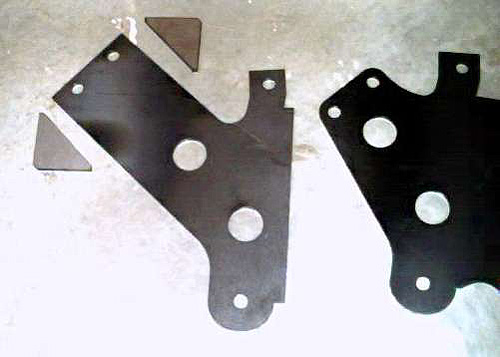
With the design established it was now time to prototype them. I was able to make a connection with a local laser cell. They laser cut the metal to precise measurements. The nice thing about going this route is that with the computer program I was able to layout the individual components to the bracket and flatten them out. I then had an electronic flat pattern that I could send to the laser cell. They can then take this file and batch it with other parts of the same material thickness. From this format it then gets sent to the laser cutting machine. It will trace out and cut on the lines that are supplied in the program it reads the file in. The only human error in this method would be my own fault. It would be in how I modeled the part.
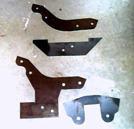
Once the parts were cut, they were ready to be formed. Forming is the process of bending the parts to create flanges and tabs for mounting the brackets. I designed the brackets so that an assembly fixture was not needed. Some complex parts would require a fixture to hold parts together when welding.


Do They Fit
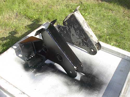
Now with the parts welded it is time to cross my fingers to see if they fit. Remember I am relying on the dimensions I took at the beginning. There was no placing the parts up to the truck to see how they fit. This is why most of the aftermarket prototype these parts so that they know how accurate they are. If there are any rework instances, then I can quickly modify the computer model to reflect these changes. If I do it this way then my truck is down for a minimal time and the repeatability of making new brackets the same, and ones that bolt on, are there on the computer model. All I would have to do is make new flat pattern CAD parts and send them back to the laser cell to be cut. And the process would continue until the parts would bolt on. This is a tuff way to do it whereas every truck will have some differences to them. Prototyping really consists of making at least 10 or more parts and trying them on a multiple of trucks. They then can get an average of what fits that particular make of vehicle.
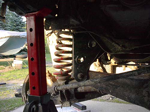
So, the next time you install a lift and a hole is just not quite in the right place remember that the part was designed for at least 10 or more vehicles of the same make. There are tolerance differences between each vehicle. Also depending on the time and money that each company puts into the brackets and prototyping the better the product will be. Since I am doing only one for my truck reworking the brackets is inevitable, no one will be perfect first time around. But who knows, things will happen that may surprise the best of us. I will let the next set of pictures explain the installation and any rework. For what it is worth, I was able to design and get the brackets built for around $200 Cdn. Providing they work out I may make a few more and try them on other trucks to see how they fit.


Now that you understand what goes into these brackets you might stop to think before you go about bad mouthing a company because the brackets don’t fit.
Contributor
These brackets were created by, and this article was written by, TRS Forum Member Joel Haywood (Forest Ranger / Copykat) and submitted to the author to post at The Ranger Station to help other Ford Ranger owners.
Dugan’s Brackets
Forum Member Dugan built his own suspension brackets for his “Mini Me” Low COG B2 Crawler/Jumper Build.

Related Articles
Build Your Own Extended Radus Arms
Sasquatch_Ryda’s Extended Radius Arms
1983-1997 Ford Ranger 4×4 Coil Spring Guide
Last Updated:
About The Author
Jim Oaks is the founder of TheRangerStation.com, the longest-running Ford Ranger resource online since 1999. With over 25 years of hands-on experience building and modifying Ford Rangers — including magazine-featured builds like Project Transformer — Jim has become one of the most trusted authorities in the Ford Ranger off-road and enthusiast space.
Since launching TheRangerStation.com, Jim has documented thousands of real-world Ranger builds, technical repairs, drivetrain swaps, suspension modifications, and off-road adventures contributed by owners worldwide. TheRangerStation.com has been referenced in print, video and online by enthusiasts, mechanics, and off-road builders looking for practical, and experience-based information.