
WHAT ARE THE AUXILIARY SWITCHES:
The auxiliary switchboard on the overhead console makes aftermarket customization easier with six prewired switches connected to the power distribution box. Each circuit is individually fused for connection of electrical accessories.
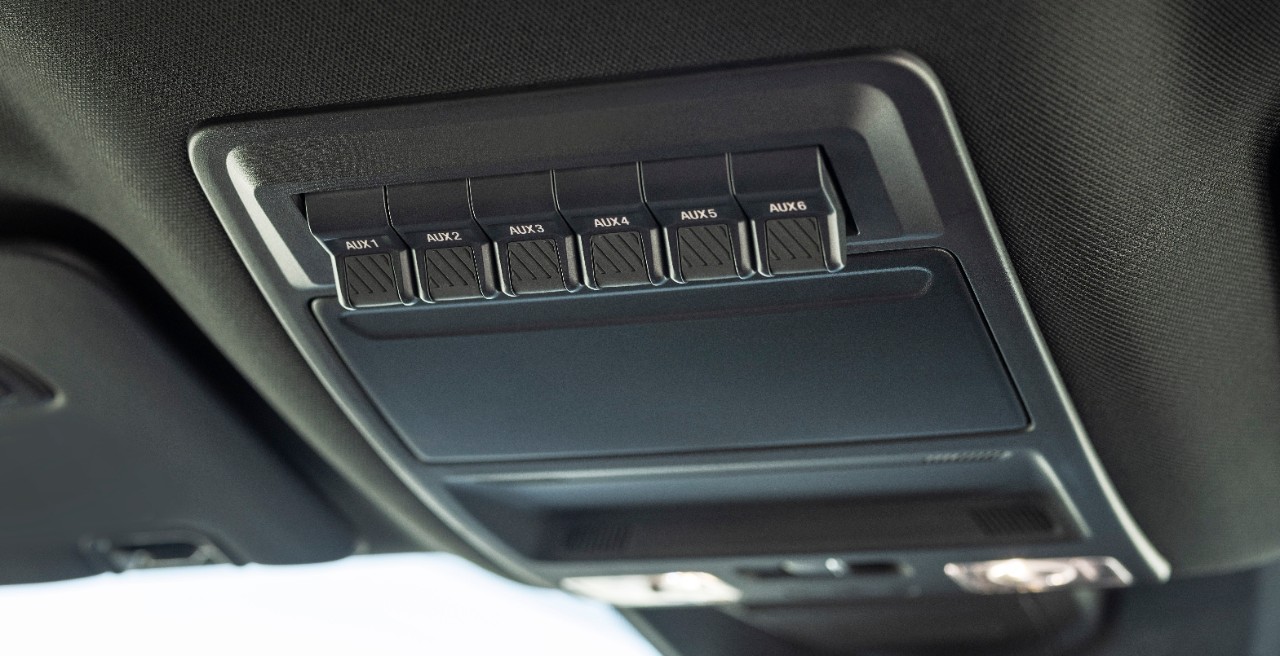
LOCATING THE AUXILIARY SWITCHES
The switches are labeled AUX 1 through AUX 6.
The auxiliary switches only operate when the ignition is in the on or off position and the delay accessory is active, whether the engine is running or not. We recommend that you leave the engine running to maintain battery charge when using the switches for an extended time or when using higher current draw accessories.
When a switch is turned on, the indicator light on the switch illuminates and the circuit provides power to the device wired to that switch.
Note: When your vehicle has a diesel engine, use the auxiliary switches only the ignition key is in the on position. Using the auxiliary switches, even for limited amounts of time, can cause your battery to drain quickly and prevent your vehicle from starting.
LOCATING THE AUXILIARY SWITCH WIRING
There are three sets of blunt-cut sealed circuits:
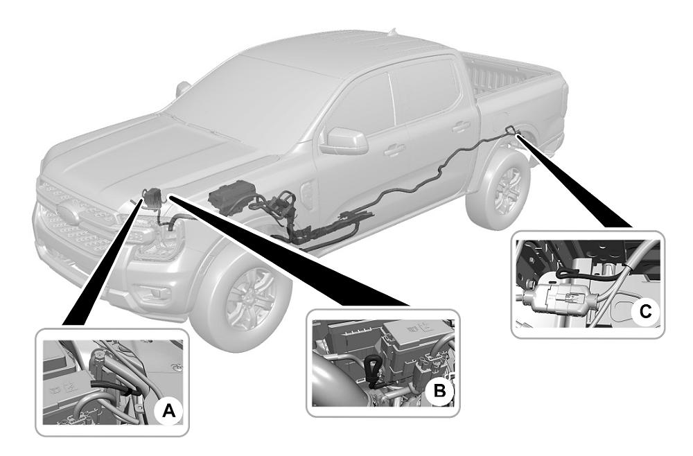
A – Circuit to radiator support. / Aux 6 Wire Location.
B – Circuit near auxiliary fuse box. / Auxiliary 1, 2, and 5 Wire Location.
C – Circuit to trailer hitch. / Auxiliary 3 and 4 Wire Location.
Additional information on fuse and relay locations is available. See your authorized dealer for service.
IDENTIFYING THE AUXILIARY SWITCH WIRING
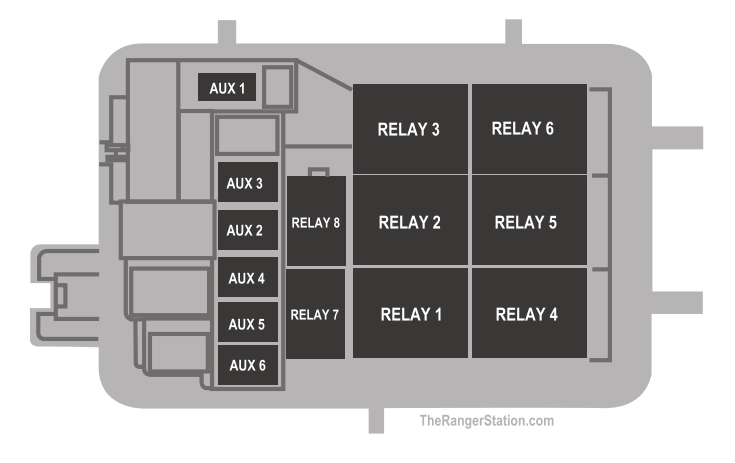
Auxiliary Switches:
The relays are coded as follows:
| Switch | Wire Color | Wire Size | Fuse | Protected Component | Blunt Cut Wire Location |
| AUX 1 | Violet / Green | 1.5 mm (2) | 5A | RELAY 1 | Vehicle Location B |
| AUX 2 | Blue / Orange | 1.5 mm (2) | 15A | RELAY 2 | Vehicle Location B |
| AUX 3 | Yellow / Orange | 1.5 mm (2) | 15A | RELAY 3 | Vehicle Location C |
| AUX 4 | Brown | 1.5 mm (2) | 15A | RELAY 4 | Vehicle Location C |
| AUX 5 | Green / Brown | 2.5 mm (2) | 25A | RELAY 5 (Driving Lamps) | Vehicle Location B |
| AUX 6 | Yellow | 2.5 mm (2) | 25A | RELAY 6 (Driving Lamps) | Vehicle Location A |
| — | — | — | — | RELAY 7 | Not Used |
| — | — | — | — | RELAY 8 | Auxiliary Switch Power |
To use these switches, you’ll need to connect your accessory (light, radio, etc) to the wire color assigned to the switch you want to use as listed above.
Ground Information:
| Power Distribution Box | Wire Color | Wire Size | Location |
| Auxiliary 3 | Black / Gray | 1.5 mm (2) | Vehicle Location C |
| Auxiliary 4 | Black / Green | 1.5 mm (2) | Vehicle Location C |
| Auxiliary 6 | Black / Yellow | 2.5 mm (2) | Vehicle Location A |
NOTE: This information is also available in your Ford Ranger owner’s manual.
Related Article
About The Author
Jim Oaks is the founder of TheRangerStation.com, the longest-running Ford Ranger resource online since 1999. With over 25 years of hands-on experience building and modifying Ford Rangers — including magazine-featured builds like Project Transformer — Jim has become one of the most trusted authorities in the Ford Ranger off-road and enthusiast space.
Since launching TheRangerStation.com, Jim has documented thousands of real-world Ranger builds, technical repairs, drivetrain swaps, suspension modifications, and off-road adventures contributed by owners worldwide. TheRangerStation.com has been referenced in print, video and online by enthusiasts, mechanics, and off-road builders looking for practical, and experience-based information.