
Understanding and Setting Proper Pinion Angle
Introduction
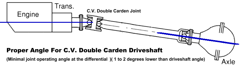
Quick Answer: Proper pinion and U-joint angles are critical to driveline smoothness and component life. In most single cardan driveshaft setups, the pinion angle should be set 1–2 degrees lower than the transmission angle to account for axle rotation under acceleration. Double cardan driveshafts require the pinion to point toward the transfer case while remaining slightly lower to prevent vibration.
When lifting a vehicle or swapping axles, setting the correct pinion angle is critical to driveline performance and reliability. Improper pinion angles are a common cause of drivetrain vibration, noise, and premature u-joint failure.
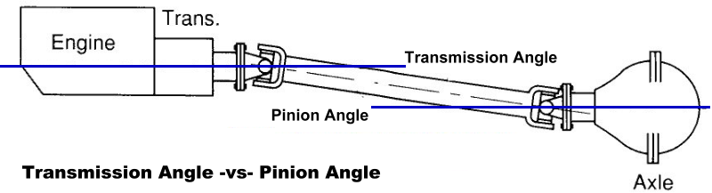
The pinion angle is the angle between the rear differential’s pinion shaft and a true horizontal line. The transmission angle is the angle between the transmission or transfer case output shaft and a true horizontal line. These two angles work together to determine the driveline’s operating geometry.
Together, the transmission angle and pinion angle form the driveline’s phase angle. Correct phasing allows the u-joints to rotate smoothly and remain properly lubricated. While a driveline can physically operate at zero degrees, u-joints require a slight operating angle so the needle bearings rotate inside the caps. Without this movement, accelerated wear and failure will occur.
This guide explains how u-joint operating angles work, how to measure transmission and pinion angles correctly, and how to set pinion angles for both single cardan and double cardan (CV) driveshafts. These principles apply to axle swaps, suspension lifts, and custom driveline setups.
U-Joint Operating Angles
The u-joint operating angle is the angle formed by two yokes connected by a cross and bearing kit. There are two kinds of u-joint angles.
The simple one plane angle found in most installations has all driveline slope confined to one plane, usually the vertical plane. The other type of driveline angle is compound angle in two planes. This is found in driveline designs where offset exists in both the vertical and horizontal planes.
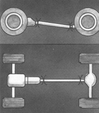
One Plane Angle Driveshafts, Side & Top View
Two Plane Angle Driveshaft, Side & Top View
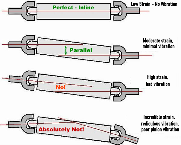
High angles combined with high RPM is the worst combination, resulting in reduced u-joint life. Too large and unequal u-joint angles can cause vibrations and contribute to U-joint, transmission and differential problems. The improper u-joint angles must be corrected.
Ideally, the operating angles on each end of the driveshaft should be equal to or within 1 degree of each other, have a 3* degree maximum operating angle and have at least 1/2 of a degree continuous operating angle.
While u-joints can operate at fairly high angles (usually up to 30* degrees), the speed at which the shaft moves provides a practical limit to the angle as follows:
|
DRIVESHAFT RPM |
MAX. NORMAL OPERATING ANGLE |
|
5000 |
3.25º |
|
4500 |
3.67º |
|
4000 |
4.25º |
|
3500 |
5.00º |
|
3000 |
5.83º |
|
2500 |
7.00º |
|
2000 |
8.67º |
|
1500 |
11.5º |
When the transmission output shaft centerline and axle input shaft centerline are parallel, the u-joint operating angle permissible is length of driveshaft divided by five.
Example: A short coupled driveshaft with a 15″ length would be limited to 3* degrees maximum operating angle. A 30″ shaft would be limited to 6* degrees.
When the transmission output shaft centerline and axle input shaft centerline intersect midway of the driveshaft, the joint angles are equal. However, due to the change to unequal joint angles during up and down axle movement, this is a more undesirable condition than parallel centerlines. In this case, the maximum u-joint operating angle is determined by dividing length of driveshaft by ten.
Example: A 30″ driveshaft with intersecting angles would have a 3* degree permissible operating angle.
Measuring Transmission & Pinion Angles
The vehicle should be checked with all the vehicles weight resting on the suspension. Park the vehicle on a level surface so that you’re not transferring weight to the front or rear, or twisting the suspension and causing angle changes.
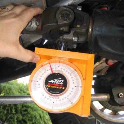
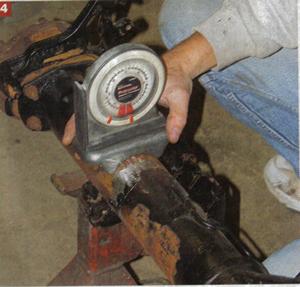
The transmission angle can be measured off the yoke (or flange if you have a flange instead of a yoke).
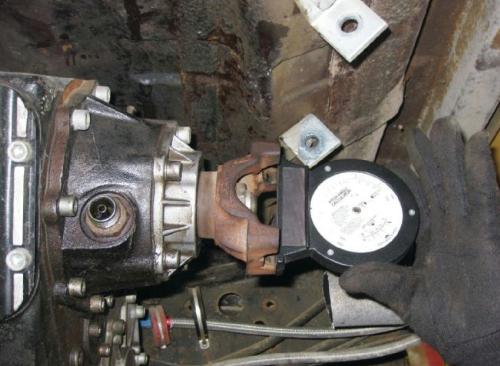
The pinion angle on the rear end is taken from the face of the pinion yoke (or flange if you have a flange instead of a yoke).
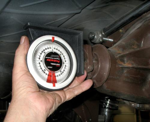
Some people have measured the angles from the bottom of the yoke instead the face of it. Just be consistent in the method you’re using, but measuring from the face is the best.
Setting Up The Axle Pinion Angle
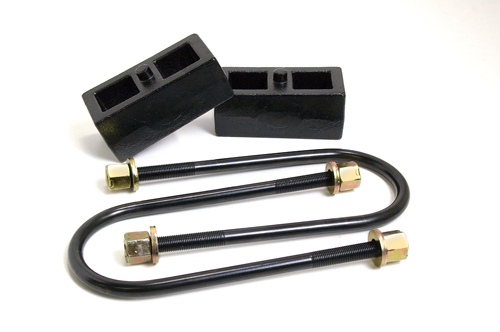
Setting up the pinion angle is generally done during an axle swap, or when lifting the vehicle. If you’ve bought a complete suspension kit, then the kit likely has correction built in to the kit. For example some kits come with lift blocks that are tapered to adjust the pinion angle.
According to Currie Enterprises, the average builder should strive for between 1* and 3* degrees between the transmission yoke (or flange) and driveshaft, and 1* to 3* degrees between the driveshaft and pinion (axle yoke or flange). Furthermore, the transmission yoke and pinion yoke should be nearly equal (between 1 and 3 degrees), but always opposite (see diagram below).
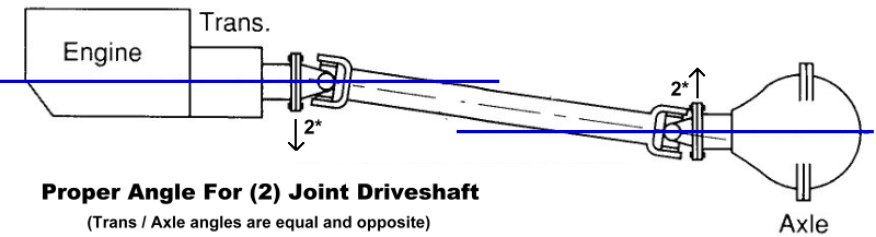
Although the angles between the transmission output shaft and driveshaft, and between the driveshaft and the pinion should be equal and opposite, it’s best to make the pinion 1* to 2* degrees lower to compensate for axle lift during acceleration.
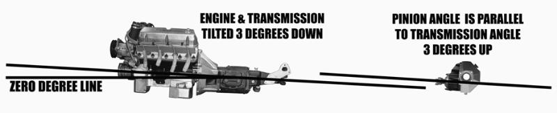
If you look at the diagrams below, you’ll see that in the first diagram, the axle pinion and transmission yoke are equal but opposite. The transmission points down 3* degrees, and the axle points up 3* degrees. This is referred to as being in phase.
But under acceleration, the axle twists up causing the angles to be out of phase.

This is why you should consider pointing the axle down 1* to 2* degrees.
Getting the transmission and pinion out of phase will cause driveshaft vibration and premature failure of your u-joints.
Don’t point your axle pinion at the transmission or transfer case unless you’re using a double carden driveshaft.
Measurement Example
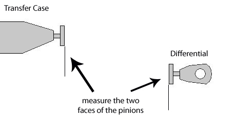
As an example, if you measured the transfer case yoke (flange) and got 86* degrees, and measured the differential and got a measurement of 92* degrees, your angle would be minus 6 degrees
E.g. 86-92= -6
For a rear differential this would mean the axel would need to be rolled forward 6 degrees.
Welding The Spring Perches
One you have your pinion angle figured out, set the yoke (or flange) at 90* degrees and your spring perches to the desired angle. Or, you can set your pinion to the desired angle, and set your perches level. Once you have them set, weld them in place.
Driveshaft Angles
People feel they need to measure their driveshaft angles when setting up pinion angles. Some people will tell you that you only need to worry about setting the pinion angle based on the transmission yoke angle. But a driveshaft that’s angled to steep could actually call for a double carden driveshaft (see below).
Driveshaft’s should not exceed 12* degrees for a single carden driveshaft. If so, you need to switch to a double carden driveshaft.
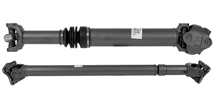
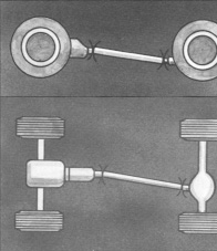
(double carden driveshaft top – single carden driveshaft bottom)
U-joints will not survive over 30* degrees. So you need to consider wheel travel and how much the angles will change at extreme angles.
The Ford Bronco II pinion is set around 17* degrees and uses a double carden driveshaft.
An extended cab Ford Ranger is set at 6* degrees. Although it comes with a 2-piece driveshaft, many owners switch to a 1-piece driveshaft after installing a suspension lift.
Constant Velocity (C.V) (Double Carden) Driveshafts
The real benefit to a C. V. (double cardan) drive shaft is smoother operation at higher operating angles and longer life. The C.V. assembly works by intersecting the joint angles at the center pivot point and delivering a smooth rotational power flow or surface velocity through the drive line. Therefore, with this type of driveline it is important to roll the differential upward so that you have minimal joint operating angle at the differential end.
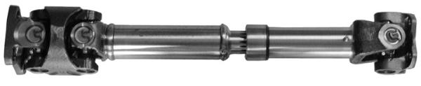
(Constant Velocity (Double Carden) Driveshaft)
When using a double carden driveshaft, the axle pinion angle needs to be 2* degrees less than the driveshaft angle. This is the only situation where you don’t try to set the pinion and equal but opposite to the transmission angle.
The pinion angle should follow the driveshaft with double carden driveshafts….
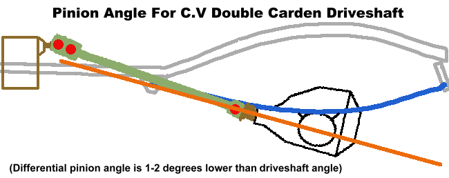
But you should set it at 1* to 2* degrees lower to compensate for axle twist under acceleration.
In the photo above, you can see that the axle pinion is parallel to the transfer case angle with the single carden driveshaft.
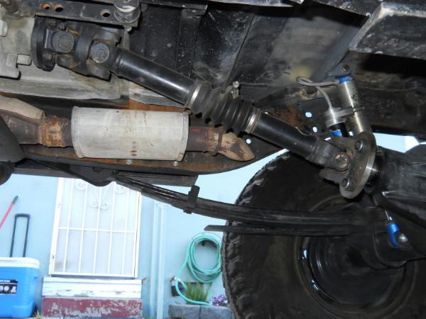
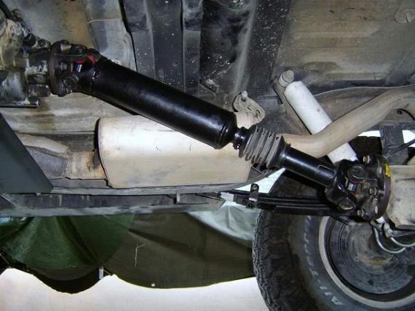
In the photo above, you can see that the axle pinion points up towards the transfer case with the double carden driveshaft.
Correcting Pinion Angles
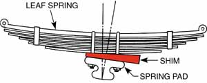
The recommended method for correcting severe u-joint operating angles depends on the vehicle suspension or driveline design. On vehicles with leaf springs suspension, thin wedges called axle shims can be installed under the leaf springs of single axle vehicles to tilt the axle and correct u-joint operating angles. Wedges are available in a range of sizes to change pinion angles. On vehicles with tandem axles, the torque rods can be shimmed. Torque rod shims rotate the axle pinion to change the u-joint operating angle. A longer or shorter torque rod may be available from the manufacture if shimming is not practical. Some torque rods are adjustable.
As a general rule, the addition or removal of a 1/4″ shim from the rear torque arm will change the axle angle approximately 3/4 of a degree. A 3/4 of a degree change in the pinion angle will change the u-joint operating angle about 1/4 of a degree.
Always take the time to call the vehicle manufacturer if there are unusual u-joint operating angle problems.
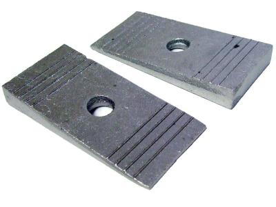
Leaf spring shims
Frequently Asked Questions
What happens if pinion angles are incorrect?
Incorrect pinion angles can cause driveline vibration, accelerated U-joint wear, and premature failure of transmission and differential components. Severe angle mismatch can also cause noise under load.
Can a driveline run with zero degrees of pinion angle?
While a driveline can physically operate at zero degrees, U-joints require a slight operating angle for proper needle bearing lubrication. Without it, bearings do not rotate and wear rapidly.
What is the maximum safe U-joint operating angle?
Most single cardan U-joints should operate below 12 degrees. Angles exceeding this typically require a double cardan (CV) driveshaft. U-joints generally fail at angles near 30 degrees.
Should pinion angles be equal and opposite?
For single cardan driveshafts, the pinion and transmission angles should be nearly equal and opposite, with the pinion set 1–2 degrees lower to compensate for axle rotation during acceleration.
When is a double cardan driveshaft required?
A double cardan driveshaft is recommended when driveshaft operating angles exceed safe limits for a single cardan joint or when suspension lift height creates steep driveline angles.
Overview – What Did We Learn
Single Carden Driveshafts – Measure the angle on the transmission yoke (or flange), and set the pinion angle on the axle 1* – 2* degrees lower. Transmission points down, axle points up.

Double Carden Driveshaft – The pinion should point up towards the transmission (or transfer case) when using a double carden driveshaft. The pinion should be 1* to 2* lower then the driveshaft angle.
Driveshaft Angles – Driveshaft angles exceeding 12* degrees should use a double carden driveshaft.
U-Joint Angles – U-joints need a slight angle for proper lubrication. Without the correct angles, the needle bearings in the u-joint caps do not rotate. Those needle bearings need to rotate in order for the u-joint to operate reliably and smoothly. These u-joint angles should always be at least 1-degree to avoid wearing out the yoke bearings. U-joints fail at 30* degrees.
Pinion Angles (SIngle Carden Driveshaft) – The pinion angle should be the opposite of the transmission (or transfer case) angle. If the transmission points down 5* degrees, the axle pinion should point up 5* degrees. And then, allow 1* to 2* for axle twist under acceleration, so a better angle at the pinion may be to point it up 4* degrees.
Pinion Angle (Double Carden Driveshaft) – The pinion should point up towards the transmission (or transfer case) when using a double carden driveshaft. The pinion should be 1* to 2* lower than the driveshaft angle.
Also Check Out:
Last Updated:
About The Author
Jim Oaks is the founder of TheRangerStation.com, the longest-running Ford Ranger resource online since 1999. With over 25 years of hands-on experience building and modifying Ford Rangers — including magazine-featured builds like Project Transformer — Jim has become one of the most trusted authorities in the Ford Ranger off-road and enthusiast space.
Since launching TheRangerStation.com, Jim has documented thousands of real-world Ranger builds, technical repairs, drivetrain swaps, suspension modifications, and off-road adventures contributed by owners worldwide. TheRangerStation.com has been referenced in print, video and online by enthusiasts, mechanics, and off-road builders looking for practical, and experience-based information.