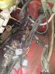
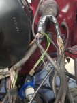
Long time lurker, first time poster. I have a bit of a pickle, I have this ranger i'm preforming a 5.0 swap on, because the carbed 2.3 was just too doggy. I have it mostly assembled, and am looking to start wiring it up and now I was wondering what color wires in the engine bay are for the ignition, and run. I looked a little but i guess not too hard because this question has probably been asked 1000+ times. I only need those wires because its a carbed 5.0. Any help would be appreciated thanks.

-
 Welcome Visitor! Please take a few seconds and Register
for our forum. Even if you don't want to post, you can still 'Like' and react to posts.
Welcome Visitor! Please take a few seconds and Register
for our forum. Even if you don't want to post, you can still 'Like' and react to posts.
Wiring Confusion
- Thread starter 6 Round Bales
- Start date
")
Sponsored Ad
Sponsored Ad
TRS Events
Member & Vendor Upgrades
For a small yearly donation, you can support this forum and receive a 'Supporting Member' banner, or become a 'Supporting Vendor' and promote your products here. Click the banner to find out how.
![]()
![]()
Latest posts
-

-

-
-

-

-

-

-
 Overland Expo MTN West August 22-24, 2025
- Latest: Curious Hound
Recently Featured
Ranger Adventure Video
TRS Merchandise
Follow TRS On Instagram


