• Welcome Visitor! Please take a few seconds and Register for our forum. Even if you don't want to post, you can still 'Like' and react to posts.

No 12v at ign switch


m00k_

Member
Joined
Jul 28, 2024
Messages
11
City
Illniois
Vehicle Year
87
Transmission
Manual
I just recently picked up an 87 ranger. I decided to go ahead and test the electrics as the previous owner was in the process of 302 swapping it.

When I mention pin "X" I'll be referring to the attached photos and not official documentation. I have very little electrical experience so this may just be something obvious to everyone but me.

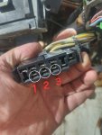
Here's my issue, I have 12v at the fuse panel (black/Orange stripe wire.) I made sure the fuse is good. I tested for continuity between this fuse and any pins on the ign switch connector.

I found continuity between the fuse panel and pin 1 in my photo but when I probe pin 1 for 12v using the same ground source as when I probed the fuse panel, I get a reading of 0v.

1000001991.jpg


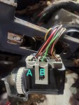
I probed around for a few different ground sources in the process of testing. Which is how I found that both pins A and B on the headlight switch have continuity with chassis ground and with all three pins circled on the ign switch connector.

1000001992.jpg


No matter which way I probe it, I cannot get a 12v reading at the ign switch. Any insight would be much appreciated.
 

Attachments

  • 1000001991.jpg
    1000001991.jpg
    87.2 KB · Views: 65
  • 1000001992.jpg
    1000001992.jpg
    110.3 KB · Views: 67
What connector is that you are holding in the picture? The ignition switch connector? And what is the color of the wire on pin 1?
 
What connector is that you are holding in the picture? The ignition switch connector? And what is the color of the wire on pin 1?
Yes it is ign switch connector. And pin 1 in the photo has two wires coming into the single pin, one black with a green stripe and one black with no stripe.
 
Last edited:
I also should mention the duraspark box has been removed, though I wouldn't have thought that'd be a factor at this stage.
 
Have you checked the fusible links, at the starter relay and near the voltage regulator?

Focus on restoring power to the ignition switch, and do that by using voltage testing instead of continuity testing.
 
Fusible link at starter relay seems to be good, I am getting 12v through. And if you're talking voltage regulator on an alternator, this vehicle does not have one currently and oddly I couldn't find a harness for one either.

I am very much a novice when it comes to using a dvom. I can check for 12v and I can check continuity. I am hoping to learn quite a bit from this project.
 
Does the truck have an amp gauge or a battery light?
 
Does the truck have an amp gauge or a battery light?
I just checked as I was home on lunch, it does have an amp meter on the instrument cluster. And if I'm honest here, I feel a bit silly. The thought never crossed my mind until I read your comment, I didn't have the cluster plugged it at all when I was poking around with my multimeter, it was sitting in the bed of the truck. (the interior is pretty much gutted but compete) I am in the process of putting it back together and wanted to test the electrics while the dash was out and had easy access to the harness.
 
Using these wiring schematics, start at the battery and follow the Black/Orange wire, and especially after Fusible Link E near the voltage regulator where it changes to Yellow and then goes to the ignition switch. Test for voltage on this circuit (around +12 volts), until you find where it ain't. It's the easiest way, on how you can find the problem, so that you can correct the failure point. And again, focus on getting power back, at the ignition switch Yellow wires.

87 pow dist 1-3.JPG

87 pow dist 2-3.JPG

87 pow dist 3-3.JPG
 
Using these wiring schematics, start at the battery and follow the Black/Orange wire, and especially after Fusible Link E near the voltage regulator where it changes to Yellow and then goes to the ignition switch. Test for voltage on this circuit (around +12 volts), until you find where it ain't. It's the easiest way, on how you can find the problem, so that you can correct the failure point. And again, focus on getting power back, at the ignition switch Yellow wires.

View attachment 114197
View attachment 114198
View attachment 114199
I found the problem. This wire was cut, not sure if it was to remove something or maybe was just damaged. Fusible link still intact as shown. I ran a test wire connecting each end and bingo! 12v as expected on the yellow battery I put wires on the ignition switch.
1000001995.jpg

My next question is can I just patch in a length of wire to repair the cut out section or is there something that needs to go in between?
 
From here, the open wire doesn't really look to be a fusible, so you should be OK with splicing a section of wire in. Use the same gauge or one size larger. Make good splices; if not soldered, use quality butt connectors and crimp them correctly.

Congratulations; you're now an official Tenderfoot Automotive Electrician.
 
He is right in the section in this diagram where the shunt is located.

index.php
 
It would be best to cover your splices with adhesive lined shrink tubing ( put in on first!).
 
From here, the open wire doesn't really look to be a fusible, so you should be OK with splicing a section of wire in. Use the same gauge or one size larger. Make good splices; if not soldered, use quality butt connectors and crimp them correctly.

Congratulations; you're now an official Tenderfoot Automotive Electrician.
Haha thanks!

Before splicing in a section, I inspected the existing wire insulation and noticed it is indeed fusible link wire. So I went to the local parts store and got a small roll of fusible link wire and used that as a splice.

Got to use my new wire crimper and connectors that I got because I was sure I'd need it on this project. Wire was been repaired crimped and protected with heat shrink.
1000001998.jpg

1000002000.jpg

1000002001.jpg
 
That's actually nice work, and you did real good catching that the wire was a fusible.

Great job!
 

Sponsored Ad


Sponsored Ad

TRS Events

Member & Vendor Upgrades

For a small yearly donation, you can support this forum and receive a 'Supporting Member' banner, or become a 'Supporting Vendor' and promote your products here. Click the banner to find out how.

Latest posts

Recently Featured

Want to see your truck here? Share your photos and details in the forum.

Ranger Adventure Video

TRS Merchandise

Follow TRS On Instagram

TRS Sponsors


Sponsored Ad


Sponsored Ad


Amazon Deals

Sponsored Ad

Back
Top