• Welcome Visitor! Please take a few seconds and Register for our forum. Even if you don't want to post, you can still 'Like' and react to posts.

negative battery cable


rumblecloud

Well-Known Member
Supporting Member
Joined
Mar 6, 2020
Messages
1,814
City
48022
State - Country
MI - USA
Vehicle Year
1994
Vehicle
Ford Ranger
Engine
4.0 V6
Transmission
Automatic
Total Lift
1-1/2 inch front leveling
Total Drop
Stock
Tire Size
31/10.50/15
My credo
What's the worst that could happen?
On my neg cable, about 17 inches from the starter end, there is A T/O. In the evtm it shows the TO going to the engine ( I think...don't have it in front of me).
When I removed the existing cable, that TO used to have some sort of connector _ totally corroded and disconnected from where it's supposed to go.
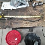
20241025_144649.jpg

1. Does anyone know where it connects to?
2. Should I recreate.this ground connector on the new cable?
It just seems like a bad idea. It was taped up and coverrd at one-time but after30 years, not so much. Lots or corrosion build up.
Thanks
 
Last edited:
I could be mistaken....

But i believe that went to the frame rail.

I think if you don't see a frame ground... it should be recreated. Even if it is a separate wire from the battery negative.
 
The drawing in the EVTM is a little misleading. The splice, S101, makes a thicker, and a thinner grounding cable. The larger goes to the engine (as G108); the smaller goes to the frame as G107. Look on your frame below the battery and you'll likely find the ring terminal from which the smaller cable corroded off from.

The way that the drawing in the EVTM is done, it makes it look like the thicker cable goes to the frame; but the engine needs a larger ground path than the frame does (think starter current draw versus a lights current draw).

You should recreate what is there, or rather, what was there originally as it came from the factory.

As it says in The Good Book, "Lack Of Ground Is The Root Of Most Evil".

. . . or something like that . . .
 
@Uncle Gump: Thanks. Wasn't sure. Still doesn't seem like a good idea, but I'll do it.

@RobbieD :
I agree. The EVTM was confusing me. Looking at 10-1 Grounds, the TO (108) goes to the Engine. And 107 goes to the frame.
I'm assuming it should be reversed and that 107 is the Engine Ground that goes to the starter/engine block. and 108 goes to the frame.

Regardless. I love having the book. It really helps. I'll look harder for the original landing spot and create a new one if I can't find it.
Need to make sure the new cable TO is well insulated so maybe it will last another ... :unsure:

You guys...thanks.
 
Looking at 10-1 Grounds, the TO (108) goes to the Engine. And 107 goes to the frame.
I'm assuming it should be reversed and that 107 is the Engine Ground that goes to the starter/engine block. and 108 goes to the frame.

Honestly, just look at it as the thicker of two ground cables should go to the engine, and the thinner one to the frame. "G107" and "G108" are physical grounding point locations, so it's best to keep them as the terminology. Where the EVTM drawing messed up was that the call-outs are reversed; it makes the take-off as engine ground, and the host cable being frame ground. If the callouts on the drawing were reversed, then the drawing would then be correct.

It's not common at all, but there are some occasional typos in the EVTMs.

A big help when reading the EVTM is to use the location views info that are there with the circuit call-out. In this case it will lead you pages 151-1 and 151-2, the "A6", "F6", etc. is the grid location on the location view drawings. It helps me, when after reading a circuit schematic I can then look at it in a location view and a lot of times being able to see the physical layout of the wiring reinforces what I'm seeing in the schematic.

The best insulation that I have found, is the heat-shrink tubing that has a hot glue lining. When you heat to shrink it the hot glue melts and some will come out the ends and harden, which makes the connection water- and moisture-proof.

You're doing good, getting that wiring straightened out.
 
I was suggesting to just run a separate wire from battery to frame of the same gauge. Opposed to breaking the insulation on your new cable to splice into that cable.

If you choose to splice... solder it. I would also use some liquid electrical tape on the connection before heat shrinking it.
 
While you are repairing the grounds...

There should also be a pigtail from battery negative to the core support.

You likely knew that... just making sure my friend.
 
As Gump mentioned, it's probably easier to use 2 separate cables instead of splicing into a nice new piece of cable. Since it's grounding wire, the insulation is merely protection against corrosion. A bare wire would work for grounding as long as it never touches a positive wire.
 
I know on the first and second gens the negative went from the battery down to the a mid line splice and a bolt to the frame, then over to the engine block. Every time that I rebuild the harness there I run separate wires. Mid line splices are just asking for corrosion. I use 4 gauge welding cable, crimp ends on, glue lined heat shrink, and then I use dielectric grease or No-Alox on the ends to keep corrosion down. I replace the body ground with a bit of 4 gauge too. No such thing as too much ground.
 

Sponsored Ad


Sponsored Ad

TRS Events

Member & Vendor Upgrades

For a small yearly donation, you can support this forum and receive a 'Supporting Member' banner, or become a 'Supporting Vendor' and promote your products here. Click the banner to find out how.

Recently Featured

Want to see your truck here? Share your photos and details in the forum.

Ranger Adventure Video

TRS Merchandise

Follow TRS On Instagram

TRS Sponsors


Sponsored Ad


Sponsored Ad


Amazon Deals

Sponsored Ad

Back
Top