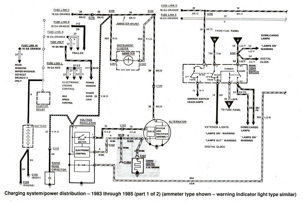
I checked the "A" terminal on the regulator and get 12v, as expected, so I think the black with orange is ok. The diagram I have more closely matches what I see on the truck. The main difference is at the regulator. The diagram you linked to has 4 wires. The diagram I have, shows 3. My regulator has 3. It also shows the STA wire as only going to the electric choke and a connected labeled "C1980". Looking up the connector, it shows as located on the "RH fender apron, near thermactor solenoids". It doesn't show what that connector goes to. So I started tracing the wire in the loom. The wire had 3 tails. One was short and as a square connector. I assume it's for the electric choke. The second goes to C102, like your diagram indicates, which is just behind the ignition module on the LH fender apron. But the other side of the connector isn't populated. And it looks like it's been that way for a long time. There aren't any cut wires nearby. I'm pretty sure it was never populated. The last tail makes it's way all the way over to the other fender and into the black ECU box. Inside, I can see that it goes to a red connector that isn't plugged into anything. Nor do I see anything for it to plug into. Was something else supposed to be in this box? It looks like there are 0 things connected to that terminal. Does it have to be connected to the regulator to function? What would the regulator do without that signal?
I also double checked that both the alternator and regulator box were grounded well. No problems there.


