
You are using an out of date browser. It may not display this or other websites correctly.
You should upgrade or use an alternative browser.
You should upgrade or use an alternative browser.
Kirbys 1991 Ranger Build Up and Solid Axle Swap
- Thread starter Kirby N.
- Start date
- Joined
- Jul 6, 2008
- Messages
- 368
- Points
- 3,101
- City
- Monument, CO
- Vehicle Year
- 1991
- Transmission
- Manual
I didn’t make that clear in the last post- I have installed limit straps now, but I didn’t before and damaged a few shocks. But thank you- I have a set of ruff stuff limit straps on there now.
- Joined
- Jul 6, 2008
- Messages
- 368
- Points
- 3,101
- City
- Monument, CO
- Vehicle Year
- 1991
- Transmission
- Manual
My kid wanted to overland with her friends for her 19th birthday. So I got it all set up on my parents land and she had a great time.

I had to do some wheeling on the way out.


I had to do some wheeling on the way out.
- Joined
- Jul 6, 2008
- Messages
- 368
- Points
- 3,101
- City
- Monument, CO
- Vehicle Year
- 1991
- Transmission
- Manual
The ranger is finally getting some love. I know, I know I bought the strong box from Behemoth Drive Train 2 years ago, but I have been super busy and haven't been able to get it installed. However, hunting season is coming and I might need some more gears. Not only that, I happened to back over into a ditch and a rock kissed my rear driveshaft and bent it. So it was finally time.
I started off by taking some pictures of the existing case and its orientation/ how low it hangs.


The strong box adds just over 4" to the existing drive train. The good news, is that it isn't going to cause any issues with the gas tank. The bad news is that it is likely going to have some issues with the floor and maybe even the brace that the seats tie to.
That and I am definitely going to have to redo the cross member.
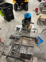
Next up, I got the case removed and assembled put the doubler on to the case dry. You might remember I had already put the sun gear and planetarium and spud shaft together. I went to a junk yard and grabbed a a couple sets of these gears so I could built the whole setup prior to installation to save time. That was a long time aThe main thing I wanted to do here is play with clocking options. I wasn't aware of it, but the front will only really go on one way because it threads on to the tranny adapter with 5 bolts and those bolts have an orientation that can't be clocked. This was a bit of a relief, because there was almost too many options and it was a bit overwhelming. Notice the outer blue section has a flat spot. This spot is oriented up toward the cab.


The middle shifter housing section is super clockable. You can see that there is 2 options that are fairly close to each other, then you can rotate to the next holes. This is really handy because you can orient the shifter lever in many places. I choose to keep it as close to the stock location as possible. It ended up being just above the other shift lever due to clearance restrictions.

A couple of things to note:
1. The o ring on the outer section to seal it up is amazing. This ensures you can do an inspection if you need to without taking the whole thing apart and reglueing it. Something that came in handy later.
2. There is 3 oil sharing holes. These are awesome because the two units share oil and you ca fill and drain just like stock. It's important to keep those free from obstructions. More on that later. It's also important to make sure the clocking position that you choose aligns the oil sharing holes in the two sections. Lucky for us, there isn't many options where they don't align and the one I chose to run with- all 3 align.
I started off by taking some pictures of the existing case and its orientation/ how low it hangs.
The strong box adds just over 4" to the existing drive train. The good news, is that it isn't going to cause any issues with the gas tank. The bad news is that it is likely going to have some issues with the floor and maybe even the brace that the seats tie to.
That and I am definitely going to have to redo the cross member.
Next up, I got the case removed and assembled put the doubler on to the case dry. You might remember I had already put the sun gear and planetarium and spud shaft together. I went to a junk yard and grabbed a a couple sets of these gears so I could built the whole setup prior to installation to save time. That was a long time aThe main thing I wanted to do here is play with clocking options. I wasn't aware of it, but the front will only really go on one way because it threads on to the tranny adapter with 5 bolts and those bolts have an orientation that can't be clocked. This was a bit of a relief, because there was almost too many options and it was a bit overwhelming. Notice the outer blue section has a flat spot. This spot is oriented up toward the cab.
The middle shifter housing section is super clockable. You can see that there is 2 options that are fairly close to each other, then you can rotate to the next holes. This is really handy because you can orient the shifter lever in many places. I choose to keep it as close to the stock location as possible. It ended up being just above the other shift lever due to clearance restrictions.
A couple of things to note:
1. The o ring on the outer section to seal it up is amazing. This ensures you can do an inspection if you need to without taking the whole thing apart and reglueing it. Something that came in handy later.
2. There is 3 oil sharing holes. These are awesome because the two units share oil and you ca fill and drain just like stock. It's important to keep those free from obstructions. More on that later. It's also important to make sure the clocking position that you choose aligns the oil sharing holes in the two sections. Lucky for us, there isn't many options where they don't align and the one I chose to run with- all 3 align.
- Joined
- Jul 6, 2008
- Messages
- 368
- Points
- 3,101
- City
- Monument, CO
- Vehicle Year
- 1991
- Transmission
- Manual
Next up, and while I haven't RTV'd any of the parts together so I still have a chance to redo it, I started working on the shifters. First off was modifying the existing lever for the rear case. I learned on my other doubler setup on my exploder, that the levers need to be the same length to achieve the same length of pull on the top side. That is one thing I messed up on the exploder. One lever traveled way too far. To be fair, i dont know which lever it was- the one on the case or the one on the linkage. But I do remember one lever really traveled a long way and the other traveled less. In fact, it was so far that the shift bezel and boot couldn't keep up. I used a boot for a doubler and a bezel for a manual tranny and tcase rbv, so it was actually pretty cool that I got them landed in that tight area back in the day. This process made me appreciate my fab skills back in the day.
On this one, I am using Behemoth's cable shifter and it will be a first for me.
I removed the extension housing off the transmission and started mocking up a facet for the cable mounts.


Initially, I thought I would start with a bracket with the cables both mounted in the same plane. What I realized quickly was that due to the shift levers being offset, I didn't have enough adjustment in the cables to mount them both in the same spot. So I had to offset them.

This got it working and would eventually be my end setup.
Next it was time to start fitting the setup in the ranger. first up, removing anything un necessary from the stock case. The floor and the case were destined to have some issues, so this would help mitigate those.


I started with a little, but eventually took off everything I could see might be a potential issue.
Here is where I made everything extra complicated. If you dont mind clocking it down a little or even leaving the case at stock clock, you would have plenty of clearance. I think my tranny rides high in my chassis too based on the way I build it to keep it out of harms way.
But you know I had these clocking options, so I had to get the best out of it. I think there was like 6 options and stock clock would hang down just a little more than before because of the slant of the drivetrain. I also trimmed the body crossmember as much as possible and even tried the ol hammer trick to make some clearance, but it just wasn't enough.
Again, this step is only necessary if you are like me and you insist on having the flattest underbelly on your rig possible- but I just had to.


Its a little excessive, but I was able to miss the seats, and it is fully contained user the middle seat/ center console area. So no one will ever see it.
On this one, I am using Behemoth's cable shifter and it will be a first for me.
I removed the extension housing off the transmission and started mocking up a facet for the cable mounts.
Initially, I thought I would start with a bracket with the cables both mounted in the same plane. What I realized quickly was that due to the shift levers being offset, I didn't have enough adjustment in the cables to mount them both in the same spot. So I had to offset them.
This got it working and would eventually be my end setup.
Next it was time to start fitting the setup in the ranger. first up, removing anything un necessary from the stock case. The floor and the case were destined to have some issues, so this would help mitigate those.
I started with a little, but eventually took off everything I could see might be a potential issue.
Here is where I made everything extra complicated. If you dont mind clocking it down a little or even leaving the case at stock clock, you would have plenty of clearance. I think my tranny rides high in my chassis too based on the way I build it to keep it out of harms way.
But you know I had these clocking options, so I had to get the best out of it. I think there was like 6 options and stock clock would hang down just a little more than before because of the slant of the drivetrain. I also trimmed the body crossmember as much as possible and even tried the ol hammer trick to make some clearance, but it just wasn't enough.
Again, this step is only necessary if you are like me and you insist on having the flattest underbelly on your rig possible- but I just had to.
Its a little excessive, but I was able to miss the seats, and it is fully contained user the middle seat/ center console area. So no one will ever see it.
bobbywalter
TRS Technical Staff
TRS Event Staff
TRS Technical Advisor
TRS Event Participant
TRS 20th Anniversary
TRS 25th Anniversary
Ugly Truck of Month
TRS Banner 2012-2015
- Joined
- Aug 9, 2007
- Messages
- 26,251
- Points
- 3,101
- City
- woodhaven mi
- Vehicle Year
- 1988
- Engine
- Transmission
- Automatic
- Total Lift
- sawzall?
- Tire Size
- 33-44
- My credo
- it is easier to fix and understand than "her"
noice..... see...i am patient.
- Joined
- Jul 6, 2008
- Messages
- 368
- Points
- 3,101
- City
- Monument, CO
- Vehicle Year
- 1991
- Transmission
- Manual
With this "modification" to the floor, I could get the case almost flat with the bottom of the frame.

And that is what I was looking for.
Next up was the patch job. I started with some 1/8 plate and some cardboard aided design.

A little welding and a spray bottle/ wet towel to keep things from getting out of hand.

The bottom turned out well too. I used a spotlight to check for holes and she is all sealed up again.

Next up was modifying the existing crossmember to support another 4" of drivetrain. I cut the 2x2 square that was on the back and added a piece of 1.75" tubing with a bend in it and a different mount for the driver rear side.

Since I had an issue with a rock and my driveshaft recently it was a good reminder that I wanted to build a skid plate for my transfer case. Even though it is tucked up nice, it it still a good idea. So the cardboard came out again.


I capped off the tubes and welded another in my crossmember for support. Here is what the final product looked like before finish welding it.

So I was making good progress and I was ready for final assembly. I heard once that right stuff was a good product to ensure nothing leaks, so I sealed up the two pieces of the strong box with their "1 minute" stuff. It was nice in a can that squeezes itself like cheese wiz, so I thought it would be great.

And that is what I was looking for.
Next up was the patch job. I started with some 1/8 plate and some cardboard aided design.
A little welding and a spray bottle/ wet towel to keep things from getting out of hand.
The bottom turned out well too. I used a spotlight to check for holes and she is all sealed up again.
Next up was modifying the existing crossmember to support another 4" of drivetrain. I cut the 2x2 square that was on the back and added a piece of 1.75" tubing with a bend in it and a different mount for the driver rear side.
Since I had an issue with a rock and my driveshaft recently it was a good reminder that I wanted to build a skid plate for my transfer case. Even though it is tucked up nice, it it still a good idea. So the cardboard came out again.
I capped off the tubes and welded another in my crossmember for support. Here is what the final product looked like before finish welding it.
So I was making good progress and I was ready for final assembly. I heard once that right stuff was a good product to ensure nothing leaks, so I sealed up the two pieces of the strong box with their "1 minute" stuff. It was nice in a can that squeezes itself like cheese wiz, so I thought it would be great.
Attachments
- Joined
- Jul 6, 2008
- Messages
- 368
- Points
- 3,101
- City
- Monument, CO
- Vehicle Year
- 1991
- Transmission
- Manual
I was able to do the final weld on the crossmember while I was waiting for the "right stuff" to cure.

I let the right stuff sit for a couple days. When I started the final install on the case, I noticed something wrong with the "right" stuff. It's hard to see in this picture, but crazy enough, the case wasn't full of oil at all, but the right stuff was letting ATF through. I mean I am glad I didn't notice it a month later and run the case out of oil, but it was pretty frustrating. I had to pull everything apart and reglue it. I ended up using some RTV specifically made for ATF.

I also ended up cutting off the mounting surface of where my tranny mounts to the crossmember and moved it passenger about 1/2". @410Fortune suggested this a long time ago when I was having driveshaft and gas tank clearance issues and it seemed like a good time to do it.

Here is how the crossmember turned out.


Next was making the cable shifters work up top. I started by tracing the stock access cover and cutting a new one out of 1/8" steel. I looked for months and found a manual transmission/ auto transfercase boot from the junk yard and I am going to use that.

The only way I could see the shifters fitting is to hang them off the back of the access cover like this. I also needed to clearance the top cover of the tranny so they would fit.

It was at about this point that I was at home in bed, and I was thinking about the new RTV that I sealed the case with that isn't leaking, and I began to wonder if it sealed up the holes between the front case and the rear case that allows them to share fluid. It wasn't leaking, but would it smoke the front bearings with those holes plugged? Did I use too much RTV? It's enough to keep a guy awake at night.
Luckily, the front part of the case (blue part) is only sealed with the o ring. So I could easily take it back apart and check, but I would have to take it completely apart. It took me a while unfortunately. but I was able to clear the holes and I am glad I did- they were definitely plugged.

I am grateful for a sweet design. It helps when you forget stuff like I do. I talked to Dillon today from behemoth and he said the front case is oiled by the push which pushed oil up around the intermediate shaft into the front case. So it likely would have had plenty of oil upfront, but might have caused some problems starving the pump or something.
I let the right stuff sit for a couple days. When I started the final install on the case, I noticed something wrong with the "right" stuff. It's hard to see in this picture, but crazy enough, the case wasn't full of oil at all, but the right stuff was letting ATF through. I mean I am glad I didn't notice it a month later and run the case out of oil, but it was pretty frustrating. I had to pull everything apart and reglue it. I ended up using some RTV specifically made for ATF.
I also ended up cutting off the mounting surface of where my tranny mounts to the crossmember and moved it passenger about 1/2". @410Fortune suggested this a long time ago when I was having driveshaft and gas tank clearance issues and it seemed like a good time to do it.
Here is how the crossmember turned out.
Next was making the cable shifters work up top. I started by tracing the stock access cover and cutting a new one out of 1/8" steel. I looked for months and found a manual transmission/ auto transfercase boot from the junk yard and I am going to use that.
The only way I could see the shifters fitting is to hang them off the back of the access cover like this. I also needed to clearance the top cover of the tranny so they would fit.
It was at about this point that I was at home in bed, and I was thinking about the new RTV that I sealed the case with that isn't leaking, and I began to wonder if it sealed up the holes between the front case and the rear case that allows them to share fluid. It wasn't leaking, but would it smoke the front bearings with those holes plugged? Did I use too much RTV? It's enough to keep a guy awake at night.
Luckily, the front part of the case (blue part) is only sealed with the o ring. So I could easily take it back apart and check, but I would have to take it completely apart. It took me a while unfortunately. but I was able to clear the holes and I am glad I did- they were definitely plugged.
I am grateful for a sweet design. It helps when you forget stuff like I do. I talked to Dillon today from behemoth and he said the front case is oiled by the push which pushed oil up around the intermediate shaft into the front case. So it likely would have had plenty of oil upfront, but might have caused some problems starving the pump or something.
Last edited:
- Joined
- Jul 6, 2008
- Messages
- 368
- Points
- 3,101
- City
- Monument, CO
- Vehicle Year
- 1991
- Transmission
- Manual
And now I have started trying to get the shifters to play nice in their final position.
Here is what they look like up top.
 I had to get 2 straight shifters on the way from behemoth and I also got a couple behemoth knobscoming. When they were oriented the other way they would interfere with the seat when it was slid forward. This way, the inside lever will interfere with the shifter in second gear.
I am actually brainstorming moving them 1" forward to get away from the sliding seat. I am going to have to shorten them down below to make it work though.
You can see in this next picture how tight the quarters are. @410Fortune 's idea of moving the drivetrain to the passenger side really came in handy here. I already had to modify one shifting mechanism down below to clear the reverse sensor. I think I could modify the other and move the shifter setup 1" forward. I would also have to shorten the shift rod by 1".

No leaks and all is well.

Here is what they look like up top.
I am actually brainstorming moving them 1" forward to get away from the sliding seat. I am going to have to shorten them down below to make it work though.
You can see in this next picture how tight the quarters are. @410Fortune 's idea of moving the drivetrain to the passenger side really came in handy here. I already had to modify one shifting mechanism down below to clear the reverse sensor. I think I could modify the other and move the shifter setup 1" forward. I would also have to shorten the shift rod by 1".
No leaks and all is well.
Jim Oaks
Just some guy with a website
Founder / Site Owner
Administrator
💻 TRS Socials
Article Contributor
TRS Event Participant
TRS 20th Anniversary
TRS 25th Anniversary
VAGABOND
TRS Banner 2010-2011
TRS Banner 2012-2015
GMRS Radio License
- Joined
- Aug 2, 2000
- Messages
- 15,980
- Points
- 7,601
- Age
- 58
- City
- Nocona
- State - Country
- TX - USA
- Other
- 2005 Jaguar XJ8
- Vehicle Year
- 2021
- Vehicle
- Ford Ranger
- Drive
- 4WD
- Engine
- 2.3 EcoBoost
- Transmission
- Automatic
- Total Lift
- 3.5-inches
- Tire Size
- 295/70/17
Looks great!
You may have mentioned this somewhere already, but why did you choose to use the Behemoth case versus their shaft and mating a 1350 to a 1354? I realize it's easier and much cleaner, but also more expensive.
You may have mentioned this somewhere already, but why did you choose to use the Behemoth case versus their shaft and mating a 1350 to a 1354? I realize it's easier and much cleaner, but also more expensive.
- Joined
- Jul 6, 2008
- Messages
- 368
- Points
- 3,101
- City
- Monument, CO
- Vehicle Year
- 1991
- Transmission
- Manual
I did the “diy thing” with a d and d kit on my exploder and there is a lot to it and also a lot more ways to screw it up- and that was a kit that provided two machined plates that bolt together and a weld in grind to fit block off plate. So it was exponentially better that just a shaft. Just a shaft would be a ton of work and a ton of ways to mess things up.
The main thing I really love about this kit is how short it is (basically impossible to build diy). The shorty kit from behemoth is along the lines of what gremilstein from rrorc built/ wanted to build back in the day. It replaces the front section of the existing case and you add in your planetaries to that section, then their intermediate shaft replaces the shaft that was in your planetaries and it is ready to mate up to the strong box. They have also thought through oiling and clocking options. Honestly, I am at a point in my life where I understand that all this is worth a lot of my hard earned cash. I would not be interested in a diy version no matter what I would save.
The main thing I really love about this kit is how short it is (basically impossible to build diy). The shorty kit from behemoth is along the lines of what gremilstein from rrorc built/ wanted to build back in the day. It replaces the front section of the existing case and you add in your planetaries to that section, then their intermediate shaft replaces the shaft that was in your planetaries and it is ready to mate up to the strong box. They have also thought through oiling and clocking options. Honestly, I am at a point in my life where I understand that all this is worth a lot of my hard earned cash. I would not be interested in a diy version no matter what I would save.
bobbywalter
TRS Technical Staff
TRS Event Staff
TRS Technical Advisor
TRS Event Participant
TRS 20th Anniversary
TRS 25th Anniversary
Ugly Truck of Month
TRS Banner 2012-2015
- Joined
- Aug 9, 2007
- Messages
- 26,251
- Points
- 3,101
- City
- woodhaven mi
- Vehicle Year
- 1988
- Engine
- Transmission
- Automatic
- Total Lift
- sawzall?
- Tire Size
- 33-44
- My credo
- it is easier to fix and understand than "her"
did the price go up? last i looked it was like 1500 for the box and i would probably make my own shifter setup... for this i was thinking that was a bargain for a ranger ....considering the cost of the atlas 4 speeds. with a manual trans this is a really nice option.
with the drive shaft issue i would consider what casey craven was doing with a two piece rear shaft and rotating the diff a bit. i am probably going that route once doubled because of the exposure to more rocks it allows.
for the work its not a bad deal for a ranger.
for full size stuff its more competitive.
to put a nwf box or most of the other diy doublers in front of a dana 300 or np205 i would say the standard black box is a better deal.
you can turnkey one for the cost of the strongbox in diy. of course lead time can be an issue depending on availability.
cant wait to see how it works out with some miles....
great to see your kids using it as well.
- Joined
- Jul 6, 2008
- Messages
- 368
- Points
- 3,101
- City
- Monument, CO
- Vehicle Year
- 1991
- Transmission
- Manual
It’s still $1500.did the price go up? last i looked it was like 1500 for the box and i would probably make my own shifter setup... for this i was thinking that was a bargain for a ranger ....considering the cost of the atlas 4 speeds. with a manual trans this is a really nice option.
with the drive shaft issue i would consider what casey craven was doing with a two piece rear shaft and rotating the diff a bit. i am probably going that route once doubled because of the exposure to more rocks it allows.
for the work its not a bad deal for a ranger.
for full size stuff its more competitive.
to put a nwf box or most of the other diy doublers in front of a dana 300 or np205 i would say the standard black box is a better deal.
you can turnkey one for the cost of the strongbox in diy. of course lead time can be an issue depending on availability.
cant wait to see how it works out with some miles....
great to see your kids using it as well.
With a stock tranny, I am not aware of other options. I don’t think the black box is compatible with our trannys. Atlas also no longer makes a Ranger compatible box. I found a used one that I considered buying, but I like this option better. 15 gears vs 10. And if the atlas breaks you would be on your own. I don’t know if a 4 speed atlas would be comparable but also much bigger.
Behemoth has said I won’t be able to break the shaft- no worries about putting the front in low and the rear on high. Duffy from d and d was clear that I should never do that or his spud shaft would break.
I really like the shorty concept. I think it is a cool design and super clean. If I had to do it over I would definitely consider making my own shifter, though I haven’t completely decided yet as my cable setup is not done yet. There is definitely the right space for a stock style shifter setup- the cables have been a challenge to fit in the space- but I almost have it dialed.
Behemoth Drivetrain
Creators of the Dana 300 and NP205 Billet Aluminum Colossus transfer case, the Borg Warner Electric to Manual conversion kit and the Strongbox underdrive series.
www.behemothdrivetrain.com
bobbywalter
TRS Technical Staff
TRS Event Staff
TRS Technical Advisor
TRS Event Participant
TRS 20th Anniversary
TRS 25th Anniversary
Ugly Truck of Month
TRS Banner 2012-2015
- Joined
- Aug 9, 2007
- Messages
- 26,251
- Points
- 3,101
- City
- woodhaven mi
- Vehicle Year
- 1988
- Engine
- Transmission
- Automatic
- Total Lift
- sawzall?
- Tire Size
- 33-44
- My credo
- it is easier to fix and understand than "her"
It’s still $1500.
With a stock tranny, I am not aware of other options. I don’t think the black box is compatible with our trannys. Atlas also no longer makes a Ranger compatible box. I found a used one that I considered buying, but I like this option better. 15 gears vs 10. And if the atlas breaks you would be on your own. I don’t know if a 4 speed atlas would be comparable but also much bigger.
Behemoth has said I won’t be able to break the shaft- no worries about putting the front in low and the rear on high. Duffy from d and d was clear that I should never do that or his spud shaft would break.
I really like the shorty concept. I think it is a cool design and super clean. If I had to do it over I would definitely consider making my own shifter, though I haven’t completely decided yet as my cable setup is not done yet. There is definitely the right space for a stock style shifter setup- the cables have been a challenge to fit in the space- but I almost have it dialed.

Behemoth Drivetrain
Creators of the Dana 300 and NP205 Billet Aluminum Colossus transfer case, the Borg Warner Electric to Manual conversion kit and the Strongbox underdrive series.www.behemothdrivetrain.com
1000 percent agree.
but, i dont have a stock powertrain. so running a dana 300 or 205 with a strong box or black box is on my all around list. that way i can keep my 410 gears. its cheaper or close to cheaper than regearing two axles and more options. i can run 31 to 44 inch tires on the road....just dont use overdrive with the big tires... 33-35 is what i usually use for street duty...unless i have military 37s...but 31-33 if i have to tow. the ol idi dont have alot of tow power.
- Joined
- Jan 14, 2008
- Messages
- 1,687
- Points
- 3,101
- Age
- 37
- City
- Clovis
- State - Country
- CA - USA
- Vehicle Year
- 1997
- Transmission
- Manual
I feel like we need to wheel together lol

Sponsored Ad

America 250
Featured Rangers
TRS Latest Video
Official TRS Merchandise
Follow TRS On Instagram


