• Welcome Visitor! Please take a few seconds and Register for our forum. Even if you don't want to post, you can still 'Like' and react to posts.

HELP!!! Charging System Trouble


rockjock

Active Member
Joined
Apr 5, 2013
Messages
32
City
fowler IN
Vehicle Year
1984
Transmission
Manual
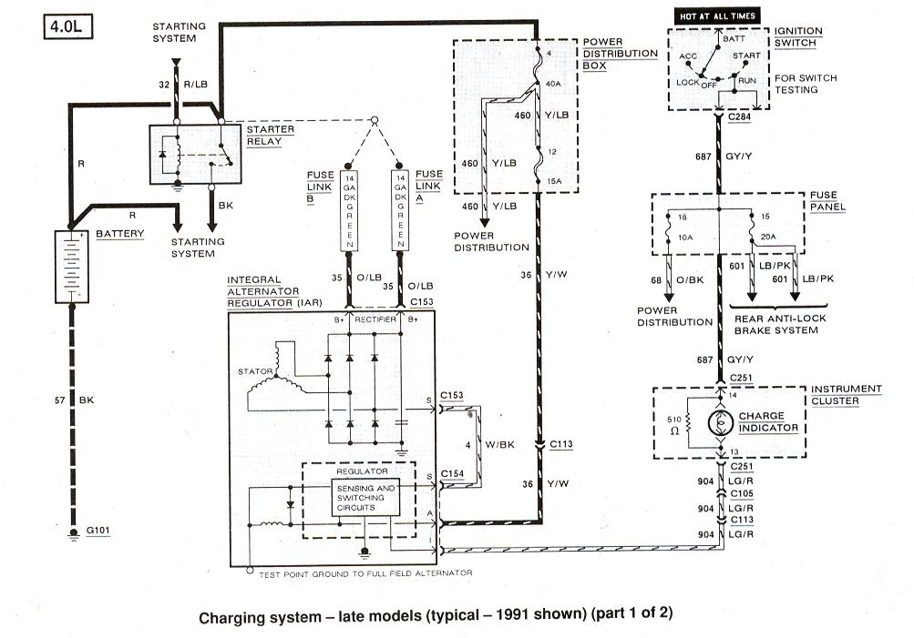
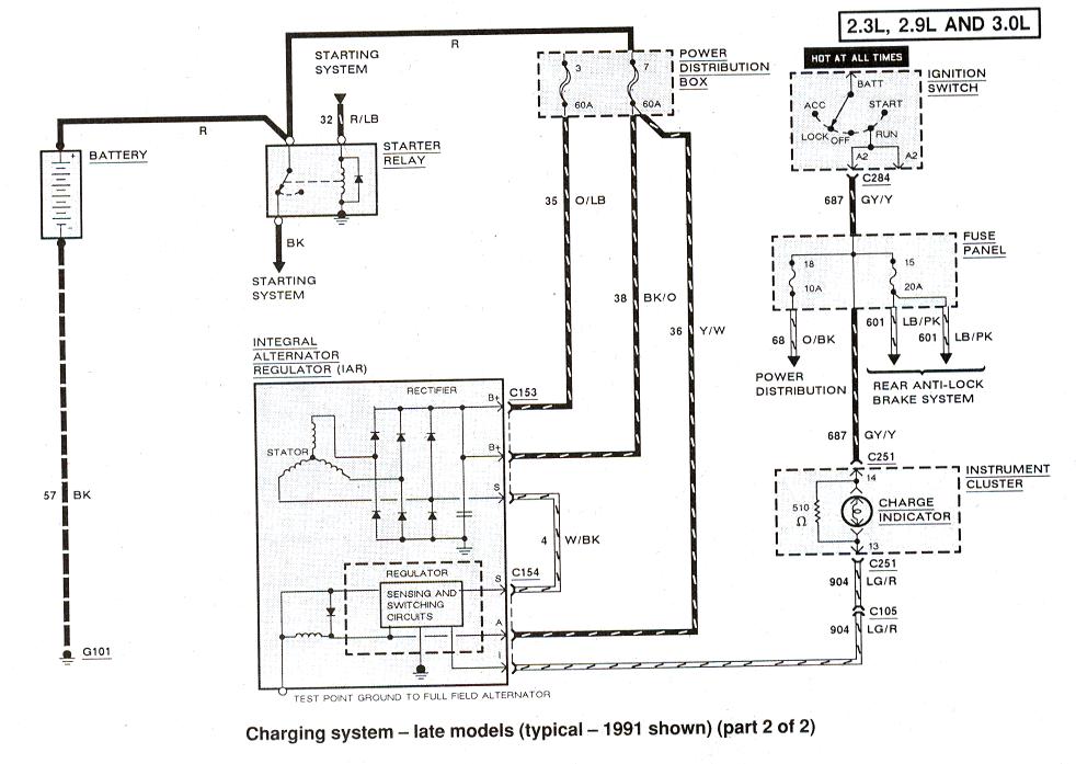
84 ford b2 original engine code was "S"
1994 4.0 from explorer ( harness and ecm, fuse panel installed in truck)
battery test good
replaced alt core tested good also
connections test good

wiring harness has to small leads to the start solenoid but solenoid only has one stud could this cause a charging issue? searched and have found nothing just got it today but cant drive it due to this and traded my daily driver cherokee for it. please guys help me not regret making this deal.

run down the road light go dim and engine dies no working gauges in dash due to motor swap im guessing?
 
http://www.therangerstation.com/tech_library/EDiagrams/files/Diagram_charging_1991_1.JPG Here is a diagram for the charging system. Does it have all the proper grounds Bat neg to engine, engine to chassis, battery neg to chassis and you can add a battery neg to alternator housing as a upgrade. The tech library also has charging system troubleshooting section all three have to be correct battery, alternator and regulator. Be sure it passes both the noload and load tests before you run it very long.
 
The power to the fuse panel goes to the battery side of the start solenoid. Pics would help.
 
On my 94 there is a fusible link in the feed from the alternator to the battery. I do not recall the color of the wire at the moment but it connects to the bottom large terminal of the solenoid on the fender. You can probably trace it back pretty quickly though as it feeds into the engine harness that runs up by the thermostat housing.

Do you have a VOM (volt ohm meter)? Trouble shooting the charging circuits is a simple and straight forward operation. I'll look back in a few times today and see if I can help. First we will need to check the continuity on that fusible link. You can do that by connecting the ohm meter to the output on the alternator and to the lower terminal on the solenoid (providing that is how yours is set up).
 
the starter solenoid is not a newer style. it looks alot like the one that was on my 85 except it only has one of the smaller studs not two like i remember. Ill shoot some pics and run through the diagrams and get right back with you guys thanks for the help.

It also looks like i need to pick up a volt meter too mine has went missing.....
 
The small terminal is for key on start only. The wire/s that go to the fuse panel should be full time hot on the battery side of the start solenoid.To simplify the charging circuit you can allways upgrade to a one wire alternator with na higher amp output for adding appliances. Just make sure any high amp draw appliances are wired direct to the battery using relays to control them and fused individually.
 
update: found the motor side of the engine ground broken. would that cause my issue????
i did re[lace it with what i had.

here is a pic of my solenoid both battery and starter are on the same side??? but turns over just fine like that though.

IMG_20130406_192840_zps81293c96.jpg
 
so fixed the engine ground, moved starter cable to the starter side of the solenoid, and attached the lead to the fuse box straight to the battery side of the solenoid.

After: (no before reading due to lack of volt meter.
12.48 at the battery while engine is running????? thought it had to be closer to 13
 
Yes if the alternator is not grounded (via the engine ground then it can not charge the battery.

The battery Red(+) cable should be on one large post of the solenoid, with the "two grey wires"(fuseable links from alt?) and the smaller red wire to the fuse box,(not hooked up now)

The other larger post should have the larger starter cable and smaller red wire with black plastic(I think that wire engages and starts the starter, which is why it is working now)

The smaller red wire that is slid onto the small stud is from the ignition key switch(via clutch or neutral switch), this activates the solenoid.

The other similar smaller red wire is for the coil, it would supply the coil with 12v only when engine is cranking, the coil normally runs on 6-8volts via a ballast resistor or wire.
This is not needed but can give coil a better spark on start up.
You could get a solenoid with the 4th post, mark "I" for ignition, or connect this wire to the starter wire side of the solenoid, NOT the 12v battery side.


12.4v is not charging battery, so yes it needs to be at 13.2v or higher, should be close to 14.2 at 2,500 RPM.
 
Last edited:
RonD that is exactly what i did i'm just lost on this one? so its possibly something so small that im over looking it. I even have a ground cable to the body of the alt.... anybody close who could shed some light in person?
 
With the engine running what is the voltage at the output of the alternator? The Orange/Black wire is the one that carries power to the battery from the alternator. There is a possibility that the fusible link (grey wire connecting orange/black to solenoid) has internal corrosion causing high resistance. Don't laugh as I have been there and done that. It appears that you have it connected correctly at he solenoid to charge the battery. If you have your wires correctly connected at the alternator, engine has a solid ground to chassis and battery, Fusible link checks out good, and you still have problems you need to start suspecting the alternator itself.

Here are a couple links that will give you some insight and are interesting reading:

http://www.pirate4x4.com/tech/billavista/Wiring/Part1/
http://www.pirate4x4.com/tech/billavista/Wiring/Part2/

Part 2 deals expressly with alternators and what makes them pop. I highly recommend it. You will know exactly what you need and where once you read it. Do let us know what you find out or if we can be of any more help.

By the way your picture was a big help.
 
Last edited:
any idea what the resistance should be on that wire? or where to find it I have a stack of manuals here chiltons and haynes for both the body (84 b2) and the drive train. (94 explorer)
 

Sponsored Ad


Sponsored Ad

TRS Events

Member & Vendor Upgrades

For a small yearly donation, you can support this forum and receive a 'Supporting Member' banner, or become a 'Supporting Vendor' and promote your products here. Click the banner to find out how.

Recently Featured

Want to see your truck here? Share your photos and details in the forum.

Ranger Adventure Video

TRS Merchandise

Follow TRS On Instagram

TRS Sponsors


Sponsored Ad


Sponsored Ad


Amazon Deals

Sponsored Ad

Back
Top