• Welcome Visitor! Please take a few seconds and Register for our forum. Even if you don't want to post, you can still 'Like' and react to posts.

Are our VSS's mostly/all 8000 ppm?


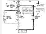
They must have simplified that unit a lot. Do you have just one output terminal?
 
As mentioned above, there are 5 output terminals, but only 2 of them output ac--which is apparently what we need.
 
<If you don't get anything without the DD unit, there must be something wrong with the signal from the VSS.>

Could be, though FWIW I had no ABS light or CEL with it and the old trans.

There is an output 3 that is 8000 ppm but AFAIK that is only with the High to Low application. Is that what yours is set on? Didn't think our 'input' from diff was that high, i.e. greater than 32,000.

Sounds like you just cut the speedo wire and used one end for input and the other for output, to/from the DD? Where, physically did you cut it?

Thanks for the info!

Sorry, I missed this post between my posts. Yes, I did cut the speedo wire and connected it to the DD units as you described. I pulled the instrument cluster out and found the wire that goes into the speedometer. I cut it in an appropriate place and spliced in before it goes into the speedometer.

I use output 1 which is indicated to be 'calibrated AC output signal' with the settings I have on my DD unit. Output 2 is called 'alternate calibrated output signal'.

I only mentioned Output 3 with the 8000 ppm output because your original question was regarding 8000 ppm. I don't understand how these systems work, just read the instructions and don't do that very well sometimes.
 
Ron,

After walking away from this for a few weeks I tried again today.

With the diff ABS sensor cut away from the wiring harness, and hooked directly to the trans. VSS, wheels in the air and truck in Drive, the engine surges from I'd guess a few hundred rpm to 1000 or so. Speedo doesn't move. Sensor is putting out about 3v ac at that point. (Voltage higher when wires not connected to VSS but idle is considerably higher then.)

I gather from what you've said you think speedo should move when connected this way, though not necessarily be accurate? If diff. is moving considerably faster than trans., speedo should be quite high, I'd think? Maybe high enough to affect fueling, but I'd think speedo should be pegged, or at least bounce?

Trying to figure out if I have a problem with the speedo itself or the Dakota Digital or ???? I can get the speedo to 'bounce' once, to 15mph or so, with a few of the DD output combinations, but never a sustained reading.

Thanks!
 
Well, partial success!

I completely cut the wires at the diff ABS sensor, and ran a wire from the sensor to the Dakota Digital, and ran its output to the (cut) GY/B wire behind the speedo.

When started, speedo did work.

The problem is, I still need to send this 'corrected' signal to the PCM and GEM, and when I try that via the GY/B at the tranny connector, all the speedo does is bounce once.

I'm suspicious I've either got a ground problem, or the GEM or PCM is bad/or not happy with the way its getting the corrected signal from the DD. I've tried every possible ground permutation I can think of. Disconnecting the GEM doesn't help.

Any thoughts on how to investigate further?

Thanks.
 
Not sure where I found it but I've been staring at that diagram for weeks now. :)

It may mean nothing but I do wonder about the fact that the speedo and GEM don't show PK/O 'grounds' from the VSS, while the PCM and CC do. :icon_confused:

Feel like I'm close, just haven't figured out the last bit of the puzzle!

Thanks again.
 
Yes, not sure why PCM would have the pink wire as well as the Grey, but that could be redundant wiring because PCM needs speed signal for shifting on automatics and the cruise would be a safety issue if speed signal was "wonky"
GEM(in '97) and speedo are just monitors of the signal so not "important" in operation of vehicle systems, and both are already grounded.

VSS signal is an AC sine wave, grey is "high"(+) part of wave and Pink is "low"(-) part of wave, this means that either + or - contains the pulse(PPM) needed to set a speed.
So having both means 100% error correction, maybe that's why two wires on PCM and Cruise
 
Well FINALLY, I seem to have a working speedo! It was as simple as disconnecting the cruise control wiring, though I haven't quite worked out why that should make a difference. :icon_confused:

At this point the wiring is: at ABS sensor-- 1 wire Pi/O (cut) goes to Dakota Digital signal in, other wire G/B (not cut).

DD output goes to original VSS wiring at trans-- Gy/B. Other VSS wire Pi/O is NOT connected. (Grounding it doesn't change anything.)

My WAG at this point is that the Pi/O and Gy/B at the CC are 'backwards' and that when the CC is hooked up, it's grounding out the signal. Hmmm... maybe I can probe the connector and see which, if either, has an a/c signal?

Any thoughts?

Thanks.
 
The VSS is an AC signal which means it is a sine wave, so half the wave is above center line and half below center line.

VSS wires are not + and - because they are not DC
VSS wires are High and Low, or upper and lower for the wave part

So each High and Low wire has the same Pulse, and either wire can be used for PPM because they have the same data, the same pulse count
 
Yes I'm still confused by the Hi and Low you mention. I know ac is not + and -, but everything I've read about these types of sensors says one wire is the signal and one is ground.

So, if somewhere in the wiring harness, the signal and ground wires are being mixed that's going to cause problems--I would think. :)
 
One is Ground, the low part usually but with AC BOTH are grounds and BOTH are +

With DC, current flows in one direction, for reference lets says it flows from + to -, although school is still out on that one, lol.

So Positive terminal on battery>>>>>>>>Light bulb>>>>>>>>>>>Negative terminal on battery
So electrons "flow" thru the bulbs filament and it warms up to make light, and they flow from + to - side of bulb

AC is alternating current, so + and - "alternate", at any given moment one wire is + and the other - and then they Reverse polarity the next moment.

Electrons still "flow" thru a light bulb but back and forth to heat up the filament, not just in one direction.

So with the AC out of the VSS the High and Low alternate , so "calling one" high and the other low is just a name assigned to it, or calling one a Ground and the other + is the same thing, just a name, because they Alternate, they are BOTH high and BOTH Low
 
I'm coming more and more to the conclusion that how/where these sensors and modules are grounded is the key to my problem. Any idea where this diagram is from, and more importantly if page 104-- GROUNDS ( at the bottom of diagram), is available?

Thanks.
 

Attachments

  • Screen Shot 2016-11-24 at 8.30.18 AM.png
    Screen Shot 2016-11-24 at 8.30.18 AM.png
    117.3 KB · Views: 172
Knowing (a little) more about ac sensors brought another thought to mind: My 'signal' wire--attached to the cut R/P on the ABS sensor on the diff goes to the Dakota Digital and then to the GY/B wire that used to attach to the VSS on the tranny. From there to PCM, speedo, etc. and speedo works--as long as CC is disconnected.

The mystery is, how is the 'return' or 'low' or 'ground' getting back to the sensor? The original LG/B wire is still connected, and as far as I know, only goes to the RABS module. :icon_confused:

Thanks again!
The ground half of that circuit, and the ground half of almost all circuits in a vehicle, is completed by the body/frame/engine/transmission metal. That pink/orange wire should run between those 3 components and should connect to a screw into truck metal, called point 104.

It's good to check that the ground wires from truck metal to components are good, tight, and clean, and the main ground straps between engine, frame, and body, and finally the battery negative ground.
 
Last edited:

Sponsored Ad


Sponsored Ad

TRS Events

Member & Vendor Upgrades

For a small yearly donation, you can support this forum and receive a 'Supporting Member' banner, or become a 'Supporting Vendor' and promote your products here. Click the banner to find out how.

Latest posts

Recently Featured

Want to see your truck here? Share your photos and details in the forum.

Ranger Adventure Video

TRS Merchandise

Follow TRS On Instagram

TRS Sponsors


Sponsored Ad


Sponsored Ad


Amazon Deals

Sponsored Ad

Back
Top