• Welcome Visitor! Please take a few seconds and Register for our forum. Even if you don't want to post, you can still 'Like' and react to posts.

Another electric fan post


BobSacamano

Well-Known Member
Joined
Nov 15, 2024
Messages
58
City
Brookhaven, MS
Vehicle Year
1996
Transmission
Manual
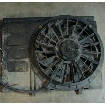
I am considering putting in an electric fan in my 1996 2.3 MT. I have a 2 speed fan from a 92 Sable, a Volvo relay from a 1994 Volvo 850 and a temp switch from a 89 BMW. If you have any experience with this, I have some questions.
1. Will my 95 amp stock alternator be able to handle this?
2. is it best to put the temp switch in the upper rad hose or the lower hose?
3. Is a 40 amp relay ok to use for the fan to come on after starting?
4. can I just not use a relay and let the fan run until the temp drops after shutting down the engine.

So I hooked it up with the fan on the ground and didn't use a relay for 12V switched. I used a heat gun to activate the switch. I don't have an infrared thermometer so I don't know the temp when it kicked on. I had a 30 amp fuse at the battery. We kept the heat gun on it until it went into high speed. The battery voltage went down to 13.9V. Does this look like a good way to go?
 
1. Yes
2. “It depends”. I found that my system works better with the switch in the lower hose.
3. Yes. 40 amps should be good.
4. I would not recommend it. The switch probably won’t last long controlling that much current. Using a relay, the temperature switch is only seeing milliamps of current - the load produced by the relay coil. The relay contacts, rated for much higher current will handle the high fan motor current.
 
Thank you so much for the reply. Two more questions.
1. Is the 30 Amp fuse at the battery enough? Should I go higher?
2. What would be a good wire to tap into for the fan to run after turning key? Preferably under the hood but I’ll do whatever is best.
 
minimum 40 amp relay. better split the power across two relays. 30 amp is fine with two.

there are so many options for control on fleebays and jungle site it is dizzying.

i tended to use the mustang 4 cylinder switch from say 87-91 for a long time to control relays, but they started getting expensive.

there should be a noise capacitor wire that is tied in with the primary ignition coil, it is red with a green stripe. you can spade terminal this to the power on the switch side of the relays and ground the switch side of relay to the mustang or whatever sender you use.

if you have ac make sure its tied in as well to run the fan on low.

i do not think you will need high. so getting away with a 95 amp should be ok. see same for mustang alternator as they were 75 amp.... most guys put high amps in anyway. but your fan is much more powerful than a normal mustang oem fan so 95 amps is minimum but very acceptable. but the taurus upgrade is the 130 amp which i suspect was due to the high capacity cooling fan.
 
Last edited:
minimum 40 amp relay. better split the power across two relays. 30 amp is fine with two.

there are so many options for control on fleebays and jungle site it is dizzying.

i tended to use the mustang 4 cylinder switch from say 87-91 for a long time to control relays, but they started getting expensive.

there should be a noise capacitor wire that is tied in with the primary ignition coil, it is red with a green stripe. you can spade terminal this to the power on the switch side of the relays and ground the switch side of relay to the mustang or whatever sender you use.

if you have ac make sure its tied in as well to run the fan on low.

i do not think you will need high. so getting away with a 95 amp should be ok. see same for mustang alternator as they were 75 amp.... most guys put high amps in anyway. but your fan is much more powerful than a normal mustang oem fan so 95 amps is minimum but very acceptable. but the taurus upgrade is the 130 amp which i suspect was due to the high capacity cooling fan.
Thank you so much! you wouldn't happen to have a diagram?
 
should be something in the tech library. look at the coil packs and trace the wire back to the noise capacitor.
 
Yes I found the wire. I have found several diagrams and they are all pretty much the same except I found one person who recommended that the relay be wired up with 30 and 85 to ground, 86 to ignition and 87 to the temp switch ground. Any thoughts on that?
I really appreciate your help.
 
This is what the fellow said about the alternate wiring:
you don't want to interrupt the main batt wire to the volvo relay with the ignition relay. because you have now limited your hi amp volvo relay to 30-40amps. you want to interrupt the ground wire on the temp sensor.
this will allow the volvo to stay connected to the full power of the battery, and turn the fans off when the key is off
30 to ground will allow the the temp sensor to have a ground when the ignition turn on
without a ground from the temp sensor the volvo relay cant energize, and that's why the fans won't run with the ignition off.

Do you agree? Would this be a better and safe way than the other?
 
That is starting to sound confusing. It would be wise to draw the circuit out to examine it for problems and avoid confusion.

This can almost be considered 2 circuits. There is a "control" circuit and a "power" circuit. The control circuit is the part that contains the relay coils and the temperature switch. This is a low current circuit. The power circuit sends battery power through the relay contacts to the fan motor. This is a high current circuit (30amps).

That is the whole purpose of relays - to use a low current circuit to control a high current circuit.
 
I would strongly recommend wiring it in accordance with the drawing supplied in the article in our tech section. If you want to do it with separate normal relays instead of using the Volvo relay bank, I can draw up a diagram for you.

 
i would not be using the Volvo relay. just paired 30s or 40s 5 pins. because of availability.


these days everything is garbage anyway....so I try to be as practical as possible.


i would wire it as advised on the Volvo. either way works fine for my application.

toe may toe........tomahtoe
 
i would not be using the Volvo relay. just paired 30s or 40s 5 pins. because of availability.


these days everything is garbage anyway....so I try to be as practical as possible.


i would wire it as advised on the Volvo. either way works fine for my application.

toe may toe........tomahtoe
I agree. But he says that he already has the Volvo relay package. So, he could use that until it fails and then go to standard relays. The biggest disadvantage would be if that happens in some remote place. But a temporary bypass could be made easily to run the fan continuously until getting to a parts store.
 
Thank y'all. You've given me a lot to think about. I think the separate normal relay diagram is in that article. I appreciate your input.
 

Sponsored Ad


Sponsored Ad

TRS Events

Member & Vendor Upgrades

For a small yearly donation, you can support this forum and receive a 'Supporting Member' banner, or become a 'Supporting Vendor' and promote your products here. Click the banner to find out how.

Latest posts

Recently Featured

Want to see your truck here? Share your photos and details in the forum.

Ranger Adventure Video

TRS Merchandise

Follow TRS On Instagram

TRS Sponsors


Sponsored Ad


Sponsored Ad


Amazon Deals

Sponsored Ad

Back
Top